Loading ...
Loading ...
Loading ...
SERVICE AND ADJUSTMENTS
HANDLE HEIGHT
NOTE: FACTORY ASSEMBLY HAS PROVIDED 141GH-
ESTHANDLE HEIGHT, SELECTHANDLE HEIGHT BEST
SUITED FOR YOUR TILLING CONDITIONS, HANDLE
HEIGHT WILL BE DIFFERENT WHEN TILLER DIGS
INTO SOIL
• tfalower Handle Height is desired, use ratchet with 112"
socket and extension to loosen Ihe four Bolts in the
Handle Mount and Engine Brackels (Fig 19)
• Slide Handle Panel to desired location
• Tighten the four Bolts securely
ENGINE
_ BRACKETS
\_k\\JI!l \ [/_ _ _ , NUTS(ALSO2
_-_-J_l__P'," tL',N _ ON LEFT SIDE
OPT,LLER
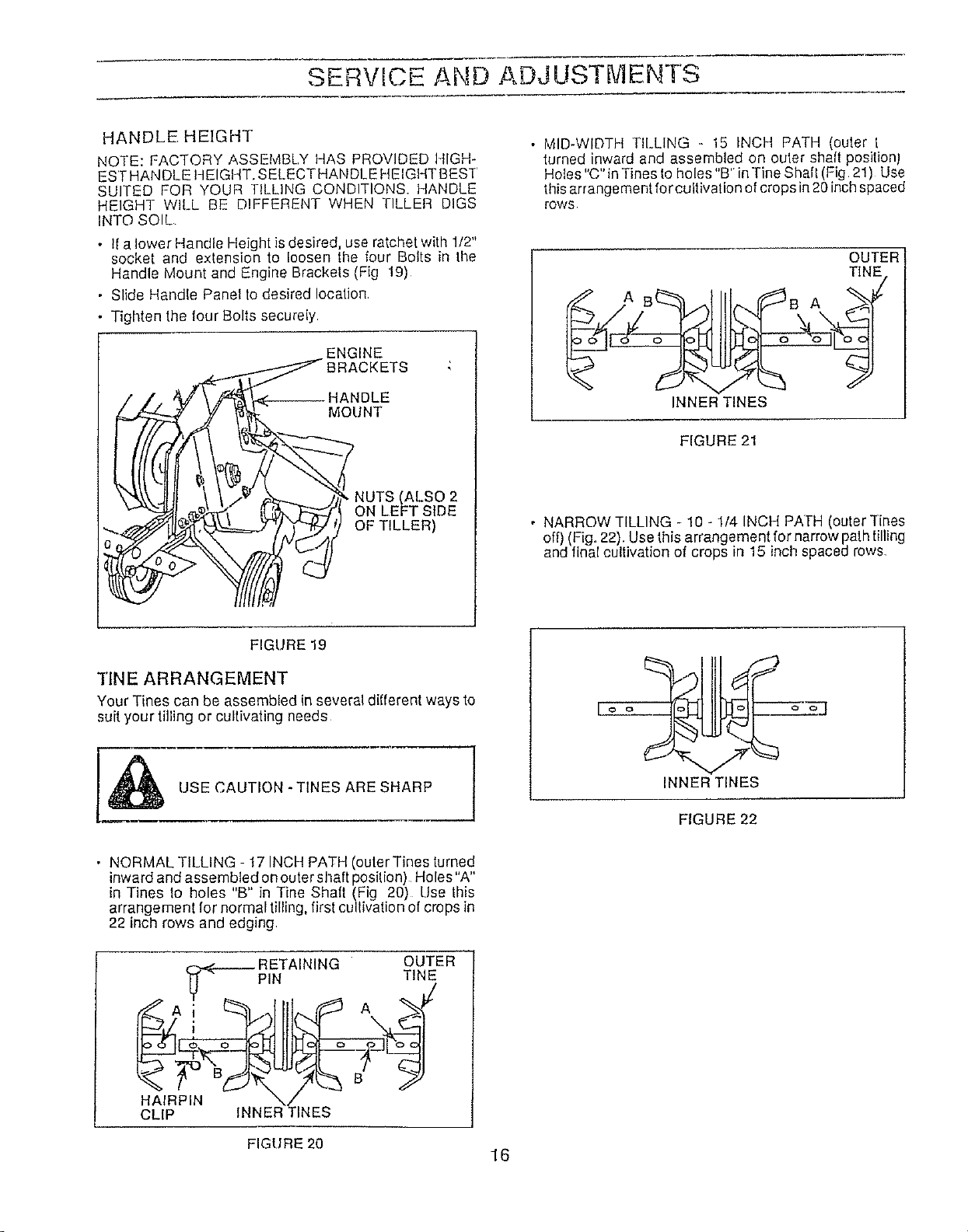
• MID-WIDTH TILLING - 15 INCH PATH (outer [
turned inward and assembled on outer shaft positionJ
Holes "C" in Tines to holes "B'"inTine Shaf! (Fig 21) Use
this arrangement forcultivation of crops in 20 inchspaced
rOWS
OUTER
TINE
AB B A
INNER TINES
FIGURE 21
• NARROW TILLING - 10 -1/4 INCH PATH (outer Tines
off) (Fig. 22). Use this arrangement for narrow pathtilling
and final cultivation of crops in 15 inch spaced rows
FIGURE 19
TINE ARRANGEMENT
Your Tines can be assembled in several different ways to
suit your tilling or cultivating needs
[I_ USE CAUTION -TINES ARE SHARP
[o o_ o ol
INNER TINES
FIGURE 22
• NORMAL TILLING - 17 INCH PATH (outer Tines turned
inward and assembled on outer shaft position) Holes"A"
in Tines lo holes "B" in Tine Shall (Fig 20) Use this
arrangemenl for normal tilling, first cultivation of crops in
22 inch rows and edging.
RETAINING OUTER
PIN TINE
HAIRPIN \/
CLIP INNER TINES
FIGURE 20
16
Loading ...
Loading ...
Loading ...