Loading ...
Loading ...
Loading ...
28
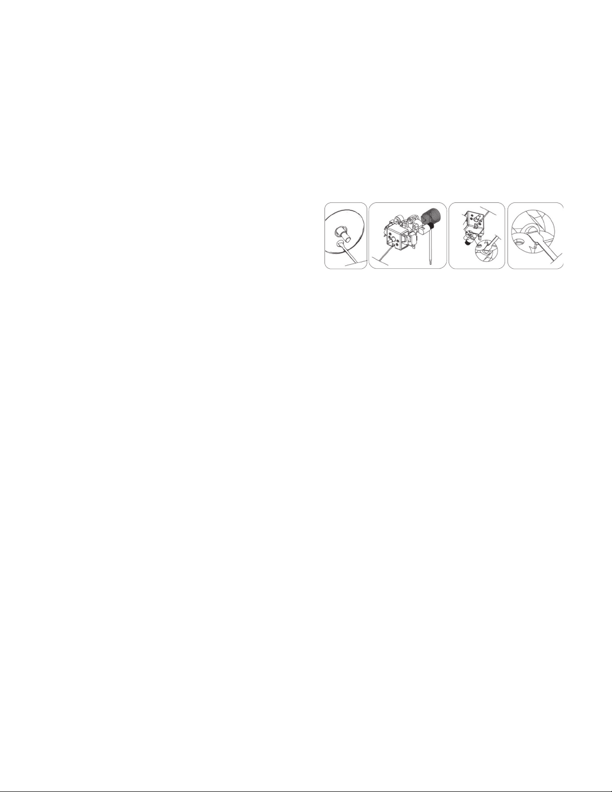
ADJUSTING THE OVEN BURNER FLAME
1) Light the burner by turning the thermostat to the 500ºF position,
2) Remove the knob by pulling straight out.
3) Remove the two (2) Phillips head screws that secure the bezel to the control panel.
4) Carefully lift the bezel away from the control panel to allow access to the access
hole below the valve stem. (see
illustration).
5) Insert the fl at head screwdriver (2.5 mm
x 75 mm) into the screw hole and turn
the bypass screw clockwise to adjust the
fl ame.
DO NOT OVERTIGHTEN.
6) Mount the knob to the valve stem.
7) Allow the oven to heat up for approximately 10 minutes then rotate the knob to the
300ºF position to operate the thermostat by-pass. Slowly screw the by-pass screw
until you obtain a fl ame of approximately 3 – 4 mm in height.
8) Carefully replace the bezel and knob ensuring not to damage wires.
OVEN VALVE
The oven control has a fl ame safety device built into the body of the thermostat.
Presence of a gas ignition source (pilot) is verifi ed by a fl ame safety probe. This fl ame
safety probe actuates the internal safety device to allow gas into the oven burner when
the oven is turned on. If there is a loss of gas ignition during operation, the fl ame safety
device will close o gas fl ow to the oven burner and pilot.
The oven burner orifi ce is located on a brass injector stud at the rear of the oven
under the oven fl oor. This orifi ce is dedicated to the gas for which the oven is to be
used. The orifi ce is not adjustable. It must be changed completely to convert from
one gas to the other. DO NOT DISCARD THE UNUSED ORIFICE. It should be saved in
order to convert the range back to its original fuel
ADJUSTING THE TOP BURNER AND OVEN FLAME
(continued)
Loading ...
Loading ...
Loading ...