Loading ...
Loading ...
Loading ...
Installation
52
5 Installation
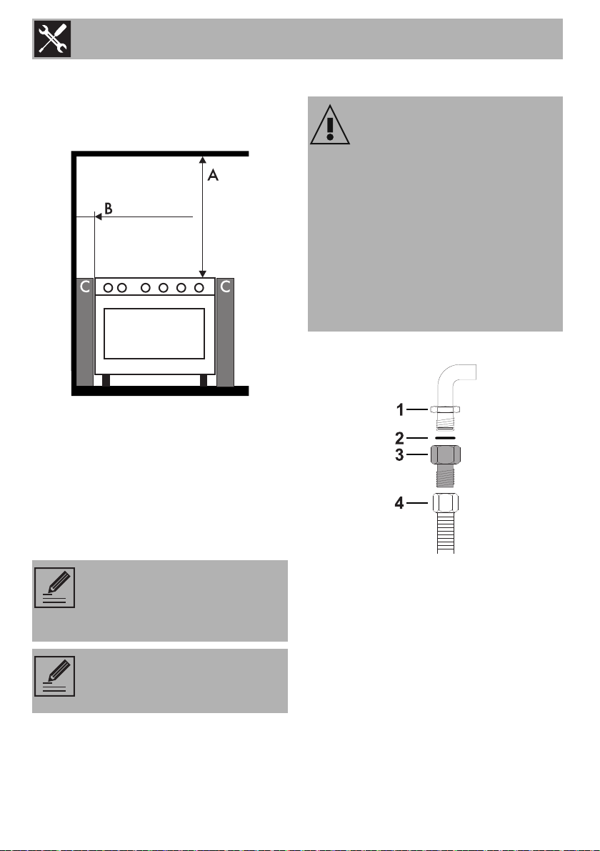
5.1 Minimum clearance to
combustible surfaces
A 600 mm (Overhead) measured from the
highest part of the highest burner and 750
mm for an exhaust fan.
B 200 mm (Vertical combustible surface)
measured form the edge of the nearest
burner.
C 10 mm (Horizontal combustible surface)
below the hob.
5.2 Gas connection
Carefully screw the hose connector 3 to the
appliance’s gas connector 1 (½” thread
ISO 228-1), placing the supplied seal 2
between them.
This appliance must be installed by an
authorised person in accordance with this
instruction manual, AS/NZS 5601.1 - Gas
installation (installation and pipe sizing),
local gas fitting regulations, local electrical
regulations, local health regulations,
Building Code of Australia and any other
government authority.
Refer to AS/NZS 5601
(Protection of a combustible
surface) if the above minimum
clearances cannot be achieved.
The appliance connection point
shall be accessible with the
appliance installed.
Gas leak
Danger of explosion
• After carrying out any operation, check
that the tightening torque of gas
connections is between 10 Nm and
15 Nm.
• If required, use a pressure regulator that
complies with current regulations.
• At the end of the installation, check for
any leaks with a soapy solution, never
with a flame.
Loading ...
Loading ...
Loading ...