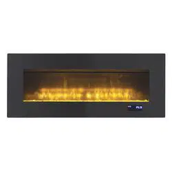

SP5736
USER MANUAL
Keep this manual for future reference
QUESTIONS, PROBLEMS, OR MISSING PARTS?
Please Contact Customer Service Before Returning to Store
Please carefully check the unit and make sure there is no damage when you open the carton.
+1-844-455-4621
www.soupro.com
• GENERAL INFORMATION
FCC/ICSES Information
Safety Instructions
Warranty
• ASSEMBLY INSTRUCTIONS
Preparation
Assembly
• FIREPLACE OPERATIONS
Operating Instructions
Care And Maintenance
Troubleshooting
Table of Contents
Safety Instructions
2
General InformatIon
Use this rebox only as described in the manual. Any other use is NOT recommended by the manufacturer and may cause
re, electric shock or injury to persons.
CaUtIon:
• If possible, ALWAYS unplug this rebox when not in use.
• DO NOT operate any rebox with a damaged cord or plug or after the heater malfunctions.
• DO NOT operate any rebox if it has been dropped or damaged in any manner. Disconnect power at service panel and have
rebox inspected by a reputable electrician before reusing.
• Any repairs to this unit should be carried out by appropriately qualied service personnel.
• Under no circumstances should this unit be modied. Parts having to be removed for servicing must be replaced prior to
operating this unit again.
• DO NOT use outdoors.
• This unit is not intended for use in bathrooms, laundry areas and similar indoor locations. NEVER place heater where it may
fall into a bathtub or other water container.
• To disconnect this unit, turn all controls to the OFF position, then remove plug from outlet.
• ONLY connect to properly grounded outlets.
• This appliance, when installed, must be electrically grounded in accordance with local codes, with the current CSA C22.1
Canadian Electrical Code or, for USA installations, follow the National Electrical Code, ANSI/NFPA NO.70.
This equipment has been tested and found to comply with the limits for Class B digital devices, pursuant to part 15 of the FCC
rules. These limits are designed to provide reasonable protection against harmful interference in a residential installation.
The equipment generates, uses and can radiate radio frequency energy and, if not installed and used in accordance with
the instructions, may cause harmful interference to radio or television reception, which can be determined by turning the
equipment off and on. The user is encouraged to try and correct the interference by one or more of the following measures:
(a) Reorient or relocate the receiving antenna
(b) Increase the separation between the equipment and the receiver
(c) Connect the equipment into an outlet on a circuit different from that to which the receiver is connected.
(d) Consult the dealer or an experienced radio/TV technician for help.
This device complies with Part 15 of the FCC rules. Operation is subject to the following two conditions:
(a) This device may not cause harmful interference, and
(b) This device must accept any interference received, including interference that may cause undesired operation.
Modications not approved by the party responsible for compliance could void user’s authority to operate the equipment.
This Class B digital apparatus complies with Canadian ICES-003.
FCC / ICES Information
2
2
4
5
7
13
14
15
Please read and understand this entire manual before attempting to assemble, operate or install the product.
IMPORTANT NOTICE
When using electrical appliances, basic precautions should always be followed to reduce the risk of re, electric shock
and injury to persons, including the following:
WARNING: Place this unit in a location that avoids direct sunlight and high temperatures.
WARNING: Plastic bags, nails, etc. should be kept out of reach of children.
WARNING: This appliance is hot when in use. To avoid burns, DO NOT let bare skin touch hot surfaces. Keep
combustible material, such as furniture, pillows, bedding, papers, clothes and curtains, at least 3 feet from the front
of the heater and keep them away from the side and rear.
WARNING: Extreme caution is necessary when any heater is used by or near children or individuals with
disabilities and whenever the replace is left operating and unattended.
WARNING: DO NOT run cord under carpeting. DO NOT cover cord with throw rugs, runners, or similar covering.
Do not route cord under furniture or appliances. Arrange cord away from traffic areas and where it will not be
tripped over.
WARNING: DO NOT insert or allow foreign objects to enter any ventilation or exhaust opening as this may cause
an electric shock or re, or damage the appliance.
WARNING: This appliance has hot and arcing or sparking parts inside. DO NOT use it in areas where gasoline,
paint or ammable vapors or liquids are used or stored. This replace should not be used as a drying rack for
clothing. Christmas stockings or decorations should not be hung in the area of it.
3
General InformatIon
• To prevent a possible re, DO NOT block any air intakes or exhaust in any manner. DO NOT use on soft surfaces, like a
bed, where opening may become blocked.
• ALWAYS plug this unit directly into a wall outlet/receptacle. NEVER use with an extension cord or relocatable power tap
(outlet/power strip).
• This heater includes an automatic protection system that will shut off the unit to prevent overheating. If the unit is at risk of
overheating, the front panel will display "E1" and a thermal cut out will shut off the heater to prevent damage or risk of re.
• DO NOT place any objects on top of rebox and top air intake vents as this will cause the unit to overheat and can cause a
re.
eleCtrICal ConneCtIon:
• A 15-amp, 120-volt, 60 Hz circuit with a properly grounded
outlet is required. Preferably, the fireplace will be on
a dedicated circuit as other appliances on the same
circuit may cause the circuit breaker to trip or the fuse
to blow when the heater is in operation. The unit comes
standard with 6-ft. three-wire cord, exiting from the rear
of the fireplace. DO NOT exceed the current rating of
the current tap. ALWAYS plug this unit directly into a wall
outlet/receptacle. NEVER use with an extension cord or
relocatable power tap (outlet/power strip).
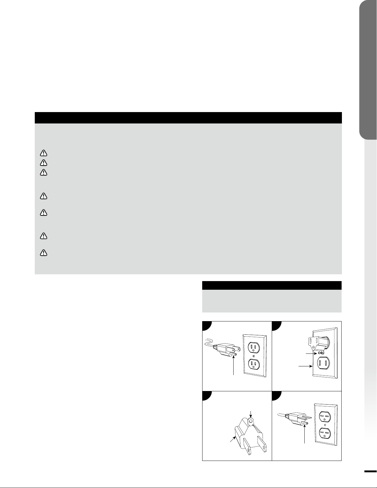
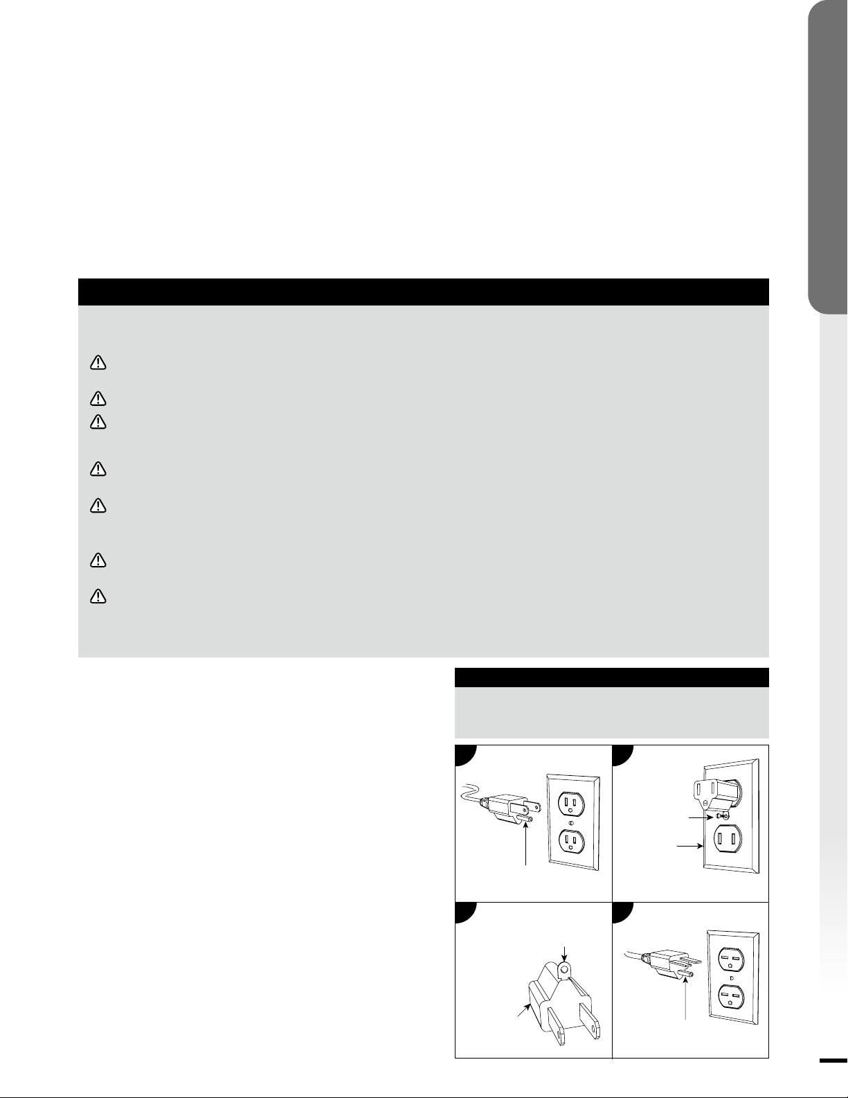
• This rebox is for use on 120 volts. The cord has a plug as
shown below. See illustration for grounding instruction. An
adapter as shown at C is available for connecting three-
blade grounding type plugs to two-slot receptacles. The
green grounding lug extending from the adapter must
be connected to a permanent ground such as a properly
grounded outlet box. The adapter should not be used if a
three-slot grounded receptacle is available.
Grounding Pin
Grounding Pin
Grounding Means
Adapter
a
C
B
D
Metal Screw
Cover of
Grounding Box
eleCtrICal SPeCIfICatIonS
Voltage:
Amps:
Watts:
120 VAC, 60 Hz
11.7 Amps
1400 Watts
Warranty
1-YEAR LIMITED WARRANTY
Soupro Limited Inc. (hereinafter referred to collectively as “the Company”) warrants that your new KOMODO Electric
Fireplace is free from manufacturing and materials defects for a period of one (1) year from date of purchase. Subject to the
following conditions and limitations:
1. The electric fireplace must be installed and operated at all times in accordance with the installation
and operating instructions furnished with the product. Any unauthorized repair, alteration, willful abuse,
accident, or misuse of the product shall nullify this warranty.
2. This warranty is non-transferable, and is made to the original owner, provided that the purchase was
made through an authorized supplier of the Company.
3. The warranty is limited to the repair or replacement of part(s) found to be defective in material or
workmanship – provided that such part(s) have been subjected to normal conditions of use and service –
after said defect is conrmed by the Company’s inspection. All replacement parts or products will be new,
remanufactured, or refurbished.
4. The Company may, at its discretion, require that any defective part(s) be returned in exchange for the
replacement part(s).
5. The Company may, at its discretion, fully discharge all obligations with respect to this warranty by
refunding the wholesale price of the defective part(s).
6. This warranty does not cover the LED light bar included with the electric replace.
7. Any installation, labor, construction, transportation, or other related costs/expenses arising from defective
part(s), repair, replacement, or otherwise of same, will not be covered by this warranty, nor shall the
Company assume responsibility for the same.
8. The owner/user assumes all other risks – if any – including but not limited to the risk of any direct, indirect
or consequential loss or damage arising out of the use, or inability to use the product, except as provided
by law.
9. All other warranties – express or implied – with respect to the unit, its components and accessories, or
any obligations/liabilities on the part of the Company are hereby expressly excluded.
10. The Company neither assumes, nor authorizes any third party to assume on its behalf, any other liabilities
with respect to the sale of the unit.
11. The warranties as outlined within this document do not apply to non-accessories used in conjunction with
the installation of this product.
12. This warranty gives you specic legal rights, and you may also have other rights which vary from state to
state.
This warranty is void if:
(a) The replace is subjected to prolonged periods of dampness or condensation.
(b) Any unauthorized alteration, willful abuse, accident, or misuse of the product.
(c) You do not have the original purchase receipt.
4
GENERAL INFORMATION
IF WARRANTY SERVICE IS NEEDED
Please Contact Customer Service
Make sure you have the following information ready:
• Warranty
• Sales Receipt
• Product Model/Serial Number
• Date of Purchase
• Location of Purchase
+1-844-455-4621
www.soupro.com

Preparation
IMPORTANT INFORMATION
1. Before you begin, locate the instructions and hardware. Be sure you have all of the parts and can identify
them.
2. To avoid scratching the finish, assemble the product on a soft, non-abrasive surface such as carpet or
cardboard.
3. Assembly of this product may require more than one person.
4. Selectalocationthatisnotsusceptibletomoisture,dustandisawayfromhightrafclocationsandthings
thatmanycatchreorblockopeningssuchasdrapes,pillows,furnitureetc.
5. It is strongly recommended that the screws be screwed into the wall studs where possible. If the wall studs
cannot be used, wall anchors must be used.
CAUTION: Enclosed wall anchors (BB) only can be use on the concrete wall.
6. Forthebesteffectinstallthereplaceoutofdirectsunlightandawayfromoverheadlighting.
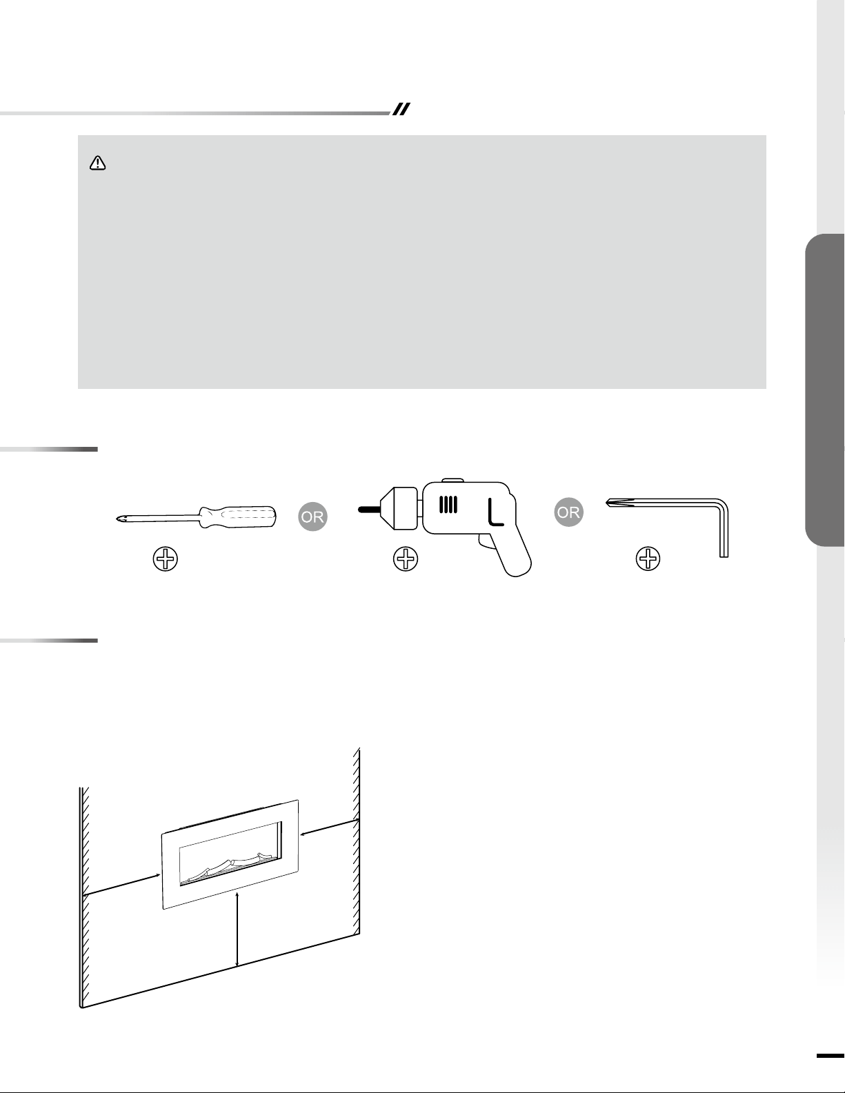
Tools Required
Philips Screwdriver Hand Drill Hex Key
5
ASSEMBLY INSTRUCTIONS
Site Selection
WARNING: This appliance is hot when in use. To avoid
burns, DO NOT let bare skin touch hot surfaces. Keep
combustible material, such as furniture, pillows, bedding,
papers, clothes and curtains, at least 3 feet from the front of
the heater and keep them away from the side and rear.
Minimum clearance of the replace to the adjacent wall
Sides ------------------------------- 6 inch / 15 cm
Floor ------------------------------- 6 inch / 15 cm
Top ------------------------------- 6 inch / 15 cm
Back ------------------------------- 0 inch / 0 cm
Select a location that is not susceptible to moisture, dust and is away from high trafc locations and things that many
catch re or block openings such as drapes, pillows, furniture etc.
Min.
6 inch
Min. 6 inch
Min. 6 inch
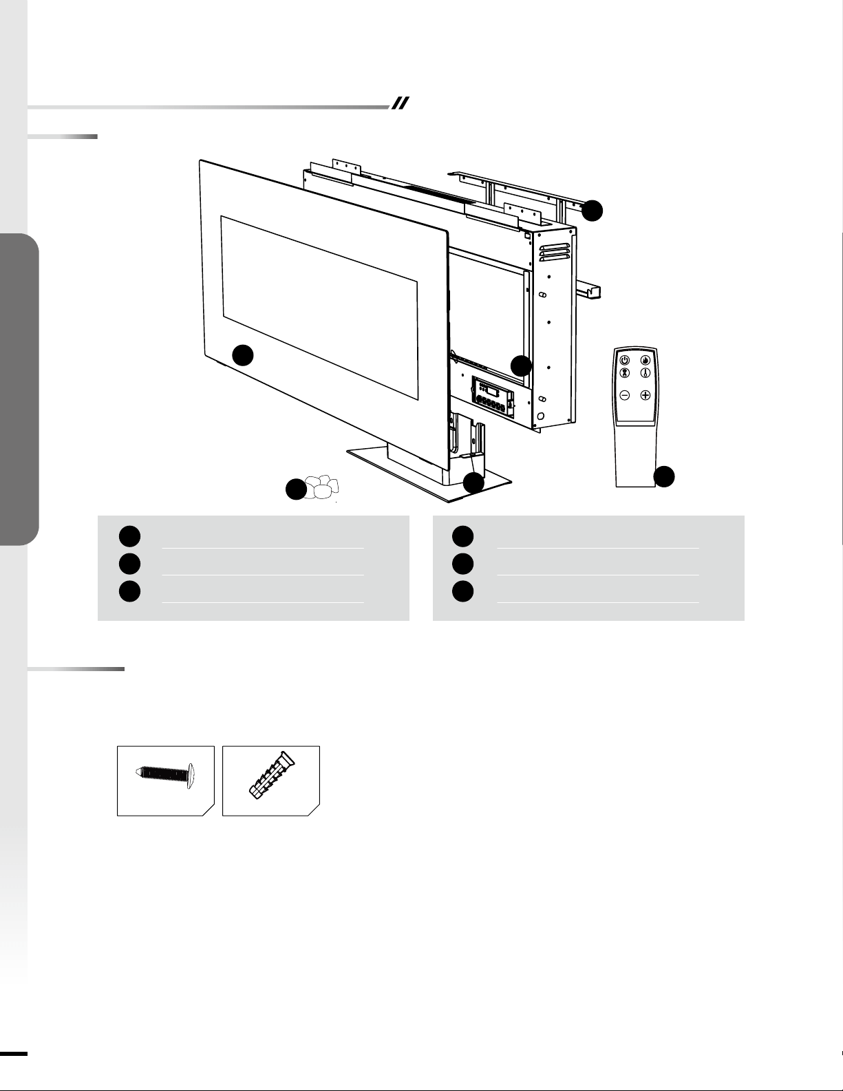
Parts List
Preparation
6
ASSEMBLY INSTRUCTIONS
x 1
x 1
x 1
A
C
B
Front Cover
Base
Fireplace
x 1
x 1
x 1
Mounting Bracket
Remote Control
Acrylic Shards
D
E
F
A
C
D
B
E
F
Number of spare hardware is indicated in ( ).
Hardware Identication
BB x 8AA x 8 + (1)

Assembly - Wall Mount Installation
7
ASSEMBLY INSTRUCTIONS
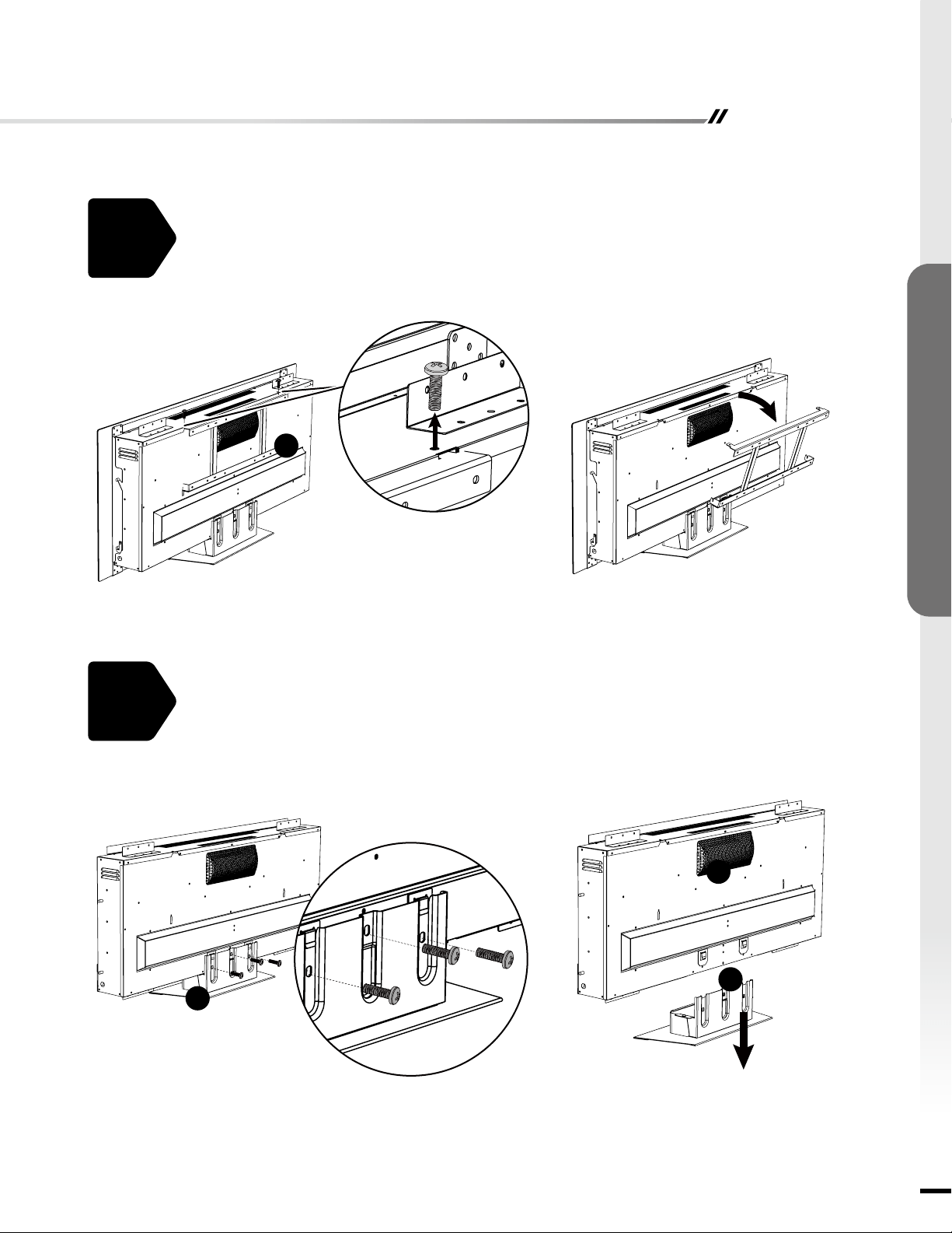
2.
1.
Remove mounting bracket (D) from back of replace (C) by unscrew two screws at the top
of the unit.
D
Remove the base (B) of replace (C) by unscrewing three screws at the rear base of the
unit.
B
B
C
8
ASSEMBLY INSTRUCTIONS
Assembly - Wall Mount Installation
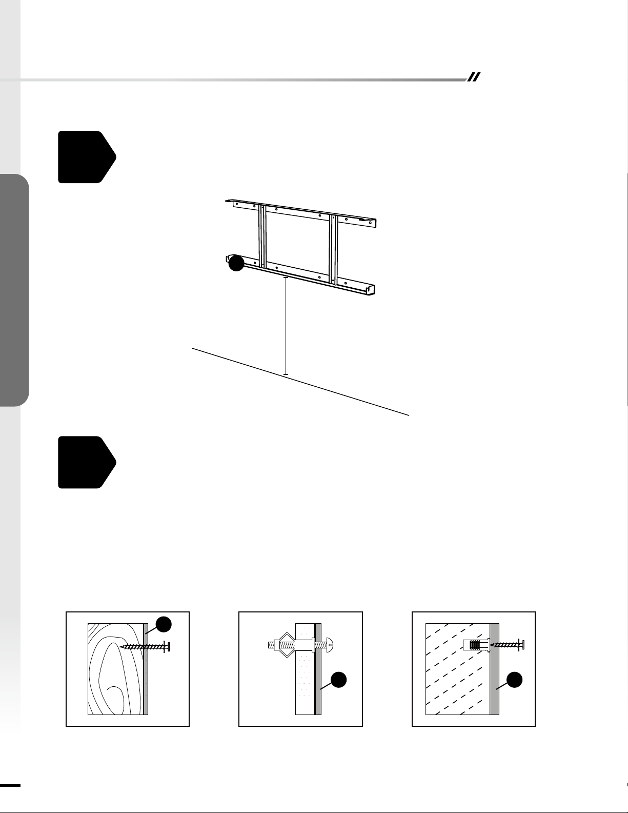
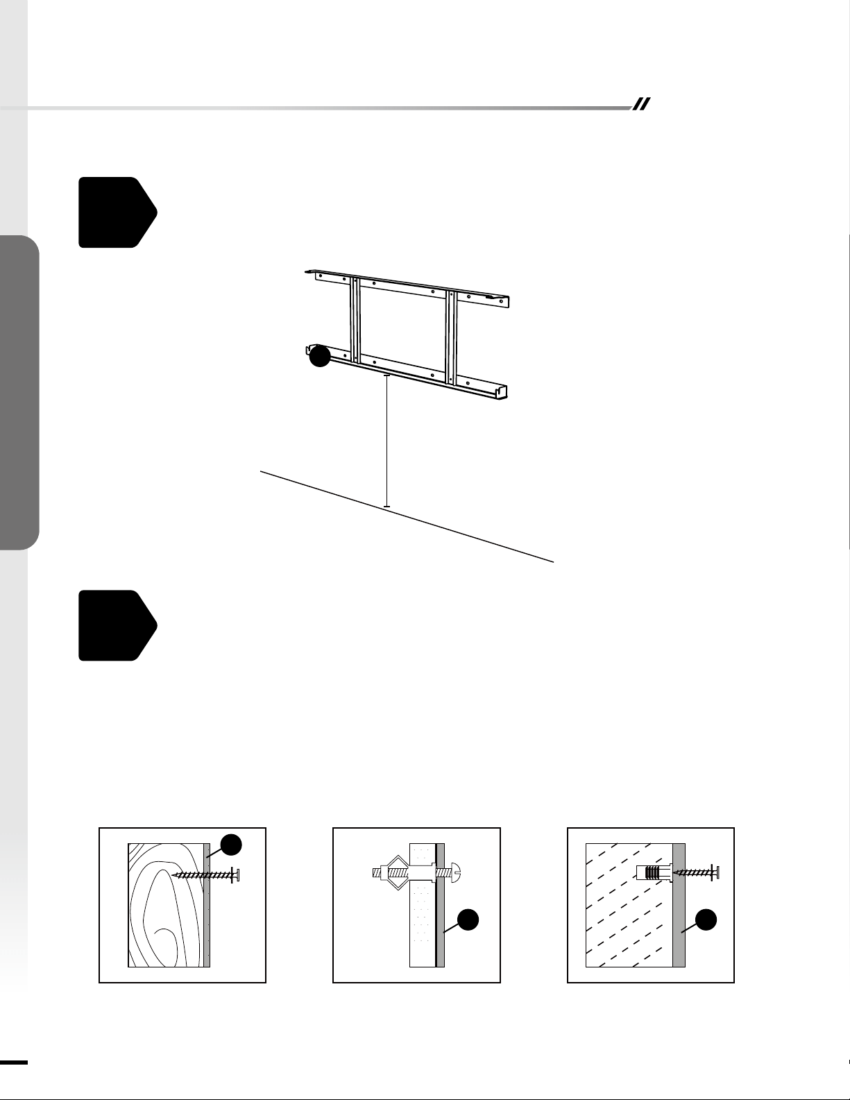
3.
4.
Choose a wall location to attach the mounting bracket (D). Position the mounting bracket (D) in the
desired location. Use a level to align the bracket and mark the eight holes with a pencil.
D
Select the hardware appropriate for mounting bracket installation.
STUD WALL
• Secure the mounting bracket (D) to wall using screws (AA) at marked stud locations.
DRYWALL
• Drill holes at marked locations and secure the mounting bracket (D) to the wall with toggle
bolts and washers (not included).
CONCRETE WALL
• Drill 5/16-inch holes at marked locations, then insert wall anchors (BB) into holes. Secure
the mounting bracket (D) to wall using screws (AA).
STUD WALL DRYWALL CONCRETE WALL
D
D D
AA
BB
AA
Minimun height: 16in
Assembly - Wall Mount Installation
9
ASSEMBLY INSTRUCTIONS
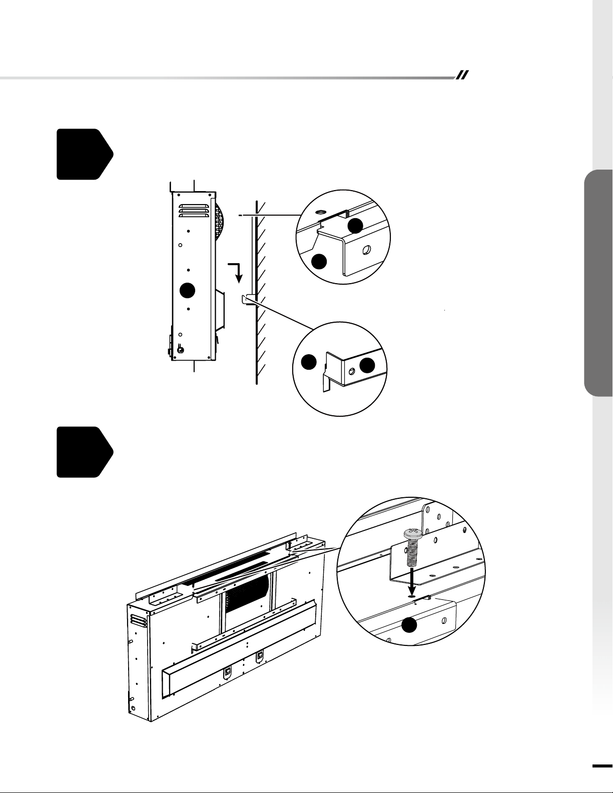
5.
6.
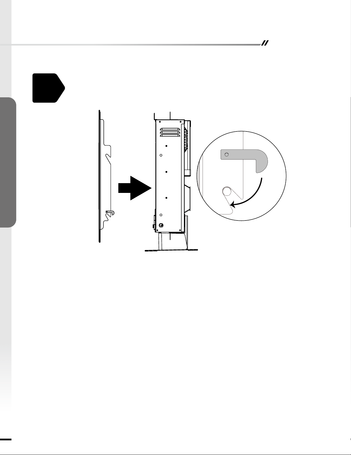
Hang the fireplace (C) on the hooks at bottom of mounting bracket (D) and push the
replace (C) into mounting bracket (D).
Re-fasten the two screws as shown.
C
C
C
D
D
D
10
ASSEMBLY INSTRUCTIONS
Assembly - Wall Mount Installation
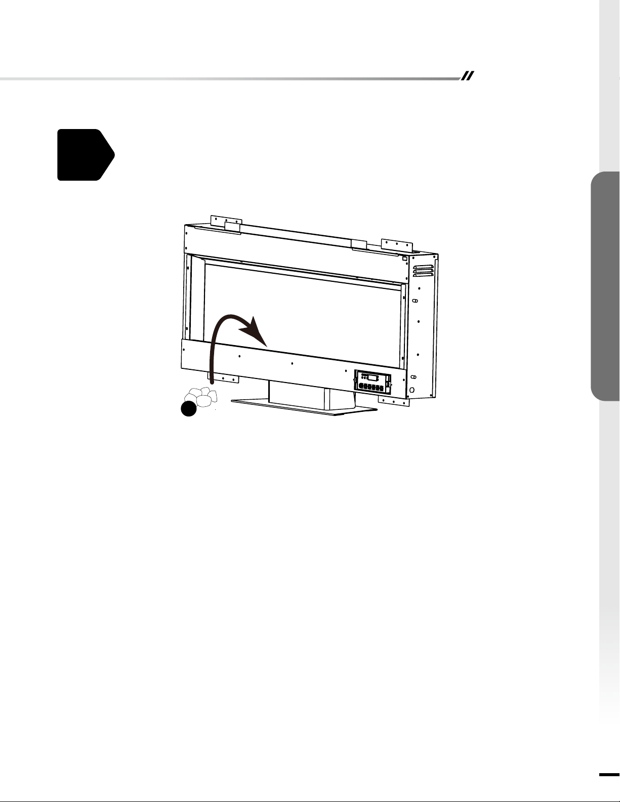
7.
Distribute the Acrylic Shards (F) evenly in the tray of the replace (C).
8.
Re-install the front glass (A) to the replace (C).
F

Assembly - Free Standing Installation
11
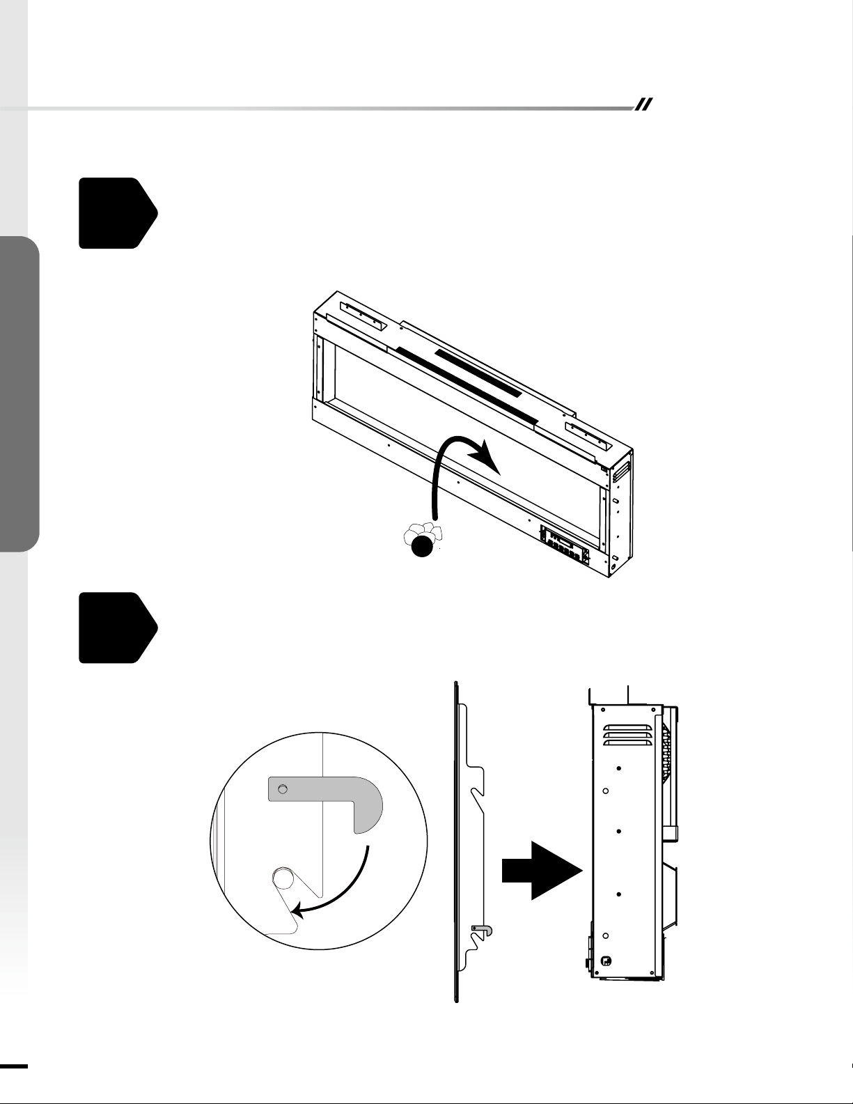
ASSEMBLY INSTRUCTIONS
1.
Distribute the Acrylic Shards (F) evenly in the tray of the replace (C).
F
12
ASSEMBLY INSTRUCTIONS
Assembly - Free Standing Installation
2.
Re-install the front glass (A) to the replace (C).
Operating Instructions
13
FIREPLACE OPERATIONS
°
F
°
C
PM
AM
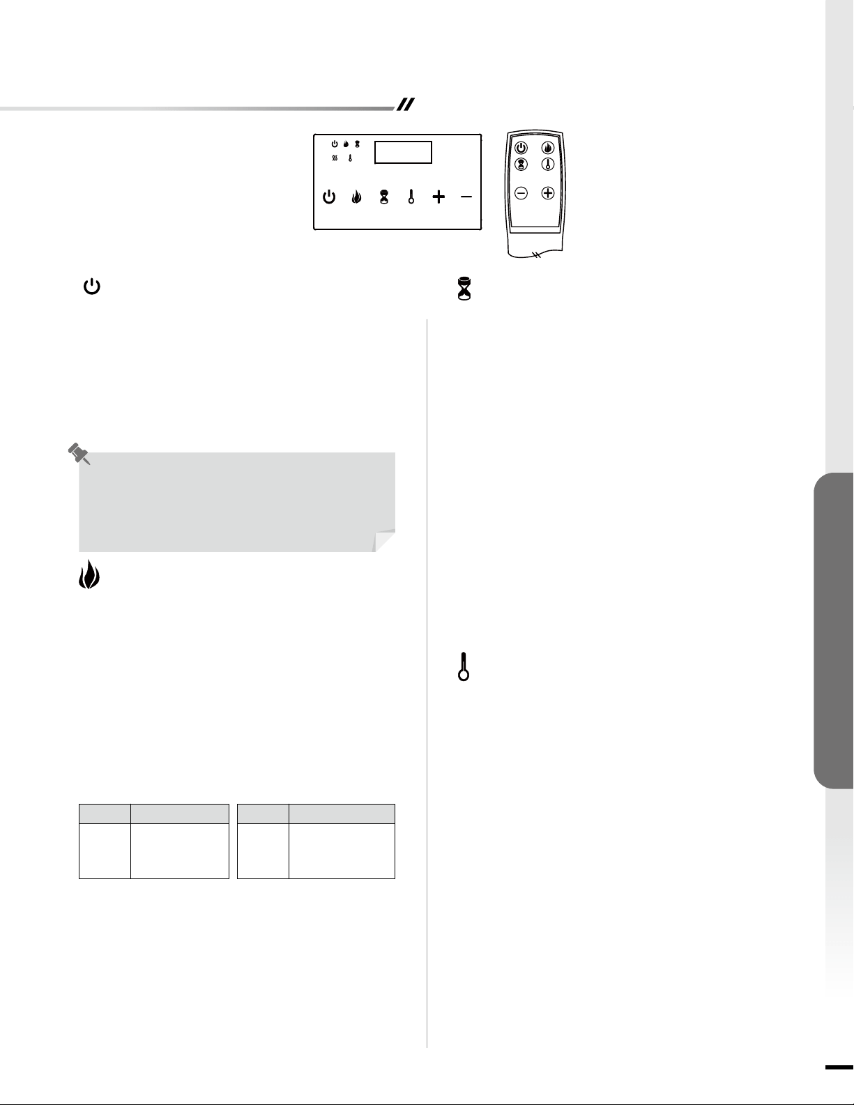
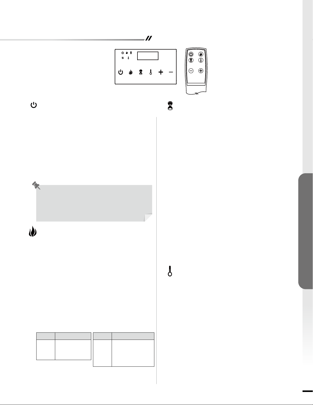
• HEATER key is used to control ON/OFF of the heater.
Push UP (“+”) or DOWN (“-”) key to to scroll through
the pre-set temperature range from 59°F (15°C) to
86°F (30°C), ON & OF (OFF). Heater will turned ON
accordingly to the set temperature. When the ambient
temperature is higher than the set temperature, heater
will automatically turned OFF.
• When the temperature is set at “ON”, heater will be
working continuously.
• When HEATER is activated, the heater & temperature
symbol will displayed.
• When the heater is ON, hold the HEATER key for 3
sec; this allow the temperature unit change from °C to
°F or °F to °C. The unit default setting is °F.
• Press the POWER button to turn ON or OFF the unit.
• When the unit is in ON mode, touch control panel light
will fully light up for 8 sec and then shut down if without
any others operation including remote control.
• When the unit is in OFF mode, the POWER symbol
LED will Semi-bright. When power OFF, unit will be
stopped, if heater is working before power OFF the
unit, fan will have 20 seconds delay to ensure heat will
not be trapped inside the unit.
• Press the ame button to cycle through the setting as:
Flame Brightness (FL), Flame Color (FC)
Flame Brightness Setting
• Press “Flame” key until FL0 / FL1 / FL2 / FL3 / FL4 /
FL5 shown on the display, and then press “+” key or “-”
key to adjust the ame brightness from level 0 to level 5.
Flame Color Setting
• Press “Flame” key until FC1 / FC2 / FC3 / FC4 / FC5 /
FC6 shown on the display, and then press “+” key or “-”
key to adjust the ame color.
Timer Setting
• Timer can be adjusted when heater is ON. It can
adjusted from 0 hour (OFF) to 9 hours with 0.5 hour
interval.
• When TIMER is activated, the symbol will be displayed.
• When TIMER digital is 0 H, TIMER function is invalided.
The TIMER symbol will automatically disappear.
• When clock is at the setting mode, hold UP (“+”) and
DOWN (“-”) keys together to select 12H or 24H mode.
The unit default setting is 24H. The AM or PM symbol
will automatically displayed when the 12H mode was
selected.
• Press the timer key can exit the setting or it will
automatically exit after 8s without any further operation.
Clock Setting
• For clock setting, hold the TIMER key for 5s, hour
display will flashing. Push UP “+” or DOWN “-” key,
Hours setting can be adjusted. Touch the TIMER key
once more, minute display will ashing. Minutes setting
can be adjusted as the same way as hours setting.
Power Button
Each time the replace is plugged in, a 5-second fan and
heater will turn on for internal check program.
The unit has a memory function with last settings for
heating level and ame brightness effect, unless the main
power to the unit has been interrupted.
Flame Button
Heater Button
Timer Button
Setting Color
FC1
FC2
FC3
Yellow
Blue
Yellow + Red
Setting Color
FC4
FC5
FC6
Yellow + Blue + Red
Yellow + Blue
Color Rotation
14
FIREPLACE OPERATIONS
Care And Maintenance
NOTE: When the heater is not in use, it should be stored in a dry location, away from possible damage. The
power cord should be stored properly to avoid contact with hot or sharp objects.
REPLACING THE REMOTE CONTROL BATTERY:
When the remote control stops operating or its range seems reduced, it is time to replace the batteries.
NOTE: The batteries should be removed if the product is to be left unused for a long time.
CAUTION:
Non-rechargeable battery is not to be recharged. Exhausted battery is to be removed from the product:
1. The battery compartment is located on the back end of the remote control.
2. Remove battery cover from the back of remote control (E).
3. Insert 2pcs AAA batteries (not included), ensuring the polarities of the battery match the inside of the battery
compartment.
4. Re-insert the battery door.
WARNING: Make sure the power is turned off before proceeding. Any electrical repairs or rewiring of this unit
should be carried out by a licensed electrician in accordance with national and local codes.
If repairing or replacing an electrical component or wiring, the original wire routing, color coding and securing
locations must be followed.
WARNING: Electrical outlet wiring must comply with local building codes and other applicable regulations to
reduce the risk of re, electrical shock and injury to persons.
WARNING: Do not use this replace if any part of it has been under water. Immediately call a qualied service
technician to inspect the replace and replace any part of the electrical system.
WARNING: Disconnect the power before attempting any maintenance or cleaning to reduce the risk of re,
electrical shock or personal injury.
WARNING: During any service of this appliance, the power to the unit must be turned off. First turn the main
power switch to the "OFF" position. Then remove the electrical plug from the wall outlet.
CLEANING INFORMATION:
• Make sure the unit is turned off, unplugged and the heating elements of heater are cool whenever you are cleaning the
heater.
• Clean the metal trim using a water-dampened, soft, and clean cloth. DO NOT use brass polish or household cleaners as
these products will damage the metal trim.
• The motors used on the fan and the flame generator assembly are pre-lubricated for extended bearing life and
require no further lubrication. However, periodic cleaning/vacuuming of the fan/heater and air intake/output vents is
recommended.
Activate Child Lock
• When the unit is ON, hold the POWER button for 10
seconds to activate the Child Lock function. "E3" will be
displayed and a "beep" will sound 3 times to indicate the
Child Lock function is activated. Then, all function keys are
locked. When pressing any button, "E3" will be displayed
to indicate the Child Lock function has been activated.
Deactivate Child Lock
• To deactivate the Child Lock function, hold the POWER
button for 10 seconds. Then, all functions keys are
unlocked.
• Control the setting of flame brightness, flame color,
mood light brightness, mood light color, timer, clock and
temperture .
Child Lock
up Button ; Down Button
Troubleshooting
Problems
1. No power, logs do not
glow.
2. "E1" is displayed on
control panel.
3. "E2" is displayed on
control panel.
4. "E3" is displayed on
control panel.
5. Fan motor continues
to blow after unit is
powered off.
6. Power cord gets warm
to the touch.
1. The unit does not have
power.
2. The overheat protection
device has been
engaged.
3. The ambient temperature
sensor is broken or not
working correctly.
4. Child Lock function is
activated.
5. Normal operation.
6. Normal operation.
Possible Causes
1. Check that unit is plugged into a standard
120 volt outlet. Then make sure power is set
at "ON" position.
2. Unplug unit, wait 5-10 minutes, then the
sensor will reset itself. Plug the unit back
in and turn on the heater. If the problem
persists, call customer service.
3. Unplug unit, wait 5-10 minutes, then the
sensor will reset itself. Plug the unit back
in and turn on the heater. If the problem
persists, call customer service.
4. To inactivate the Child Lock function, hold
the POWER button for 10 seconds.
5. This is a standard feature; the blower runs
for an additional 20 seconds to ensure heat
will not be trapped inside the unit.
6. This is normal for a heater appliance as it
requires more current to operate. Check the
connections of the appliance cord and the
outlet. Make sure the plug fits tightly into
the outlet. During use, check the plug and
outlet frequently to determine if it is HOT;
if so, discontinue use of the appliance and
consult with a qualied electrician to check
or change the overheating outlet(s).
Solutions
15
FIREBOX OPERATIONS
Care And Maintenance
Troubleshooting
Problems
1. No power, logs do not
glow.
2. "E1" is displayed on
control panel.
3. "E2" is displayed on
control panel.
4. "E3" is displayed on
control panel.
5. Fan motor continues
to blow after unit is
powered off.
6. Power cord gets warm
to the touch.
1. The unit does not have
power.
2. The overheat protection
device has been
engaged.
3. The ambient temperature
sensor is broken or not
working correctly.
4. Child Lock function is
activated.
5. Normal operation.
6. Normal operation.
Possible Causes
1. Check that unit is plugged into a standard
120 volt outlet. Then make sure power is set
at "ON" position.
2. Unplug unit, wait 5-10 minutes, then the
sensor will reset itself. Plug the unit back
in and turn on the heater. If the problem
persists, call customer service.
3. Unplug unit, wait 5-10 minutes, then the
sensor will reset itself. Plug the unit back
in and turn on the heater. If the problem
persists, call customer service.
4. To inactivate the Child Lock function, hold
the POWER button for 10 seconds.
5. This is a standard feature; the blower runs
for an additional 20 seconds to ensure heat
will not be trapped inside the unit.
6. This is normal for a heater appliance as it
requires more current to operate. Check the
connections of the appliance cord and the
outlet. Make sure the plug fits tightly into
the outlet. During use, check the plug and
outlet frequently to determine if it is HOT;
if so, discontinue use of the appliance and
consult with a qualied electrician to check
or change the overheating outlet(s).
Solutions
For more information about collection and recycling of used batteries, please contact your local municipality, your waste
disposal service or the point of sale where you purchased this item.
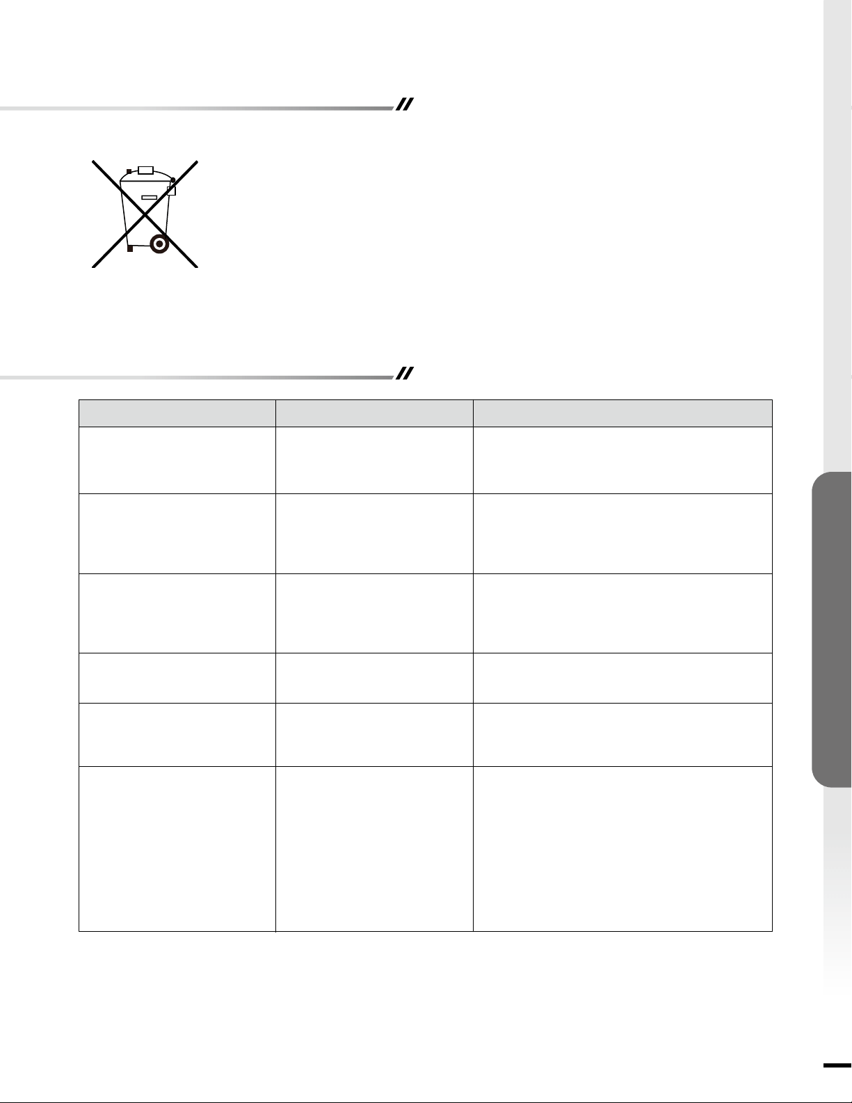
A battery may contain hazardous substances that could be endangering to the environment
and human health.
• This symbol marked on the battery and/or packaging indicates that used battery shall not be
treated as municipal waste. Instead it shall be left at the appropriate collection point for recycling.
• By ensuring the used battery is disposed of correctly, you will help prevent potential negative
consequences for the environment and human health. The recycling of materials will help to
conserve natural resources.
DISPOSAL OF USED BATTERY:

QUESTIONS, PROBLEMS, OR MISSING PARTS?
Please Contact Customer Service Before Returning to Store
Crafted in China
Distributed by Soupro Limited Inc., 72 Montgomery Court, Markham, Ontario L3R 0C1
Ver.1
+1-844-455-4621
www.soupro.com

SP5736
Conservez ce manuel pour référence future
MANUEL D'UTILISATEUR
QUESTIONS, PROBLÈMES OU PIÈCES MANQUANTES?
Contactez le service clientèle avant de le retourner au magasin
Vériez soigneusement l'appareil et assurez-vous qu'il n'y a pas de dommages lorsque vous ouvrez le carton.
+1-844-455-4621
www.soupro.com
• GENERAL INFORMATION
Informations FCC / IC
Information de securite
Garantie
• INSTRUCTIONS D’ASSEMBLÉE
Préparation
Assemblée
• OPÉRATIONS DE FOYER
Instructions d’operation
Soins et entretien
Guide de depannage
Table des matières
2
INFORMATION DE SECURITE
N’utilisez cet appareil que pour l’usage prevu dans ce manuel. Toute autre utilisation n’est PAS recommandee par le fabricant
et peut provoquer un incendie, une decharge electrique ou des blessures.
MISE EN GARDE:
•Danslamesuredupossible,debranchezTOUJOURScetappareillorsqu’iln’estpasutilise.
•N’utilisezPASunappareilmunid’unecheoud’uncordonendommagesouquiasubiunedefaillance.
•NefaitesPASfonctionnerunappareilquiesttombeouquiaeteendommagedequelquefaconquecesoit.Coupez
l’alimentationelectriqueapartirdutableaudedistributionetfaitesinspecterl’appareilparunelectricienqualieavantdele
reutiliser.
•Coneztoutereparationdecefoyerauntechnicienqualie.
•Nemodiezjamaiscefoyer.Replacezlespiecesquiontduetreretireespourl’entretienavantd’utiliserdenouveaulefoyer.
•N’utilisezPASceproduital’exterieur.
•Cetappareiln’estpasconcupouretreutilisedansunesalledebains,unesalledelavageoutoutautreendroithumide
semblable.NeplacezJAMAISl’articledansunendroitouilpourraittomberdansunebaignoireouunautrecontenantrempli
d’eau.
•Pourdebranchercetappareil,tournezlescommandesenpositiond’arret,puisretirezlachedelaprise.
•BranchezUNIQUEMENTlachesuruneprisecorrectementmisealaterre.
•Lorsdel’installation,veillezacequel’appareilsoitmisalaterreconformementauxcodeslocaux,alaplusrecenteversion
duCodecanadiendel’electricite,CSAC22.1,ouaucodenationaldel’electricite,ANSI/NFPANo70.
CetarticleaététestéetdéclaréconformeauxlimitesimposéesauxdispositifsnumériquesdeclasseB,conformémentà
l’alinéa15durèglementdelaFCC.Ceslimitessontdestinéesàassureruneprotectionraisonnablecontrelesinterférences
nuisiblesdansunenvironnementrésidentiel.Cetarticlegénère,utiliseetpeutémettredel’énergieradiofréquenceet,s’iln’est
pasinstalléetutiliséconformémentauxinstructions,risquedeprovoquerdesinterférencesnuisibleslorsdelaréception
d’émissionsderadiooudetélévision(ilsuft,pourlevérier,d’allumeretd’éteindresuccessivementl’article).L’utilisateur
devraprendrelesmesuresnécessairessuivantespourtenterd’éliminercesinterférences:
(a)reorienteroudeplacerl’antennereceptrice;
(b)accroitreladistanceentrel’appareiletlerecepteur;
(c)brancherl’appareilsuruneprisedecourantappartenantaunautrecircuitqueceluidurecepteur;
(d)obtenirdel’aideaupresdudetaillantoud’untechnicienenradioouentelevisionexperimente.
Cetappareilestconformeal’alinea15dureglementdelaFCC.Sonutilisationestsoumiseauxdeuxconditionssuivantes:
(a)cetappareilnedoitprovoqueraucuneinterferencenuisible;et
(b)cetappareildoitacceptertouteinterferencerecue,ycomprisdesinterferencessusceptiblesdecauserunfonctionnement
non desire.
Lesmodificationsnonautoriseesexpressementparlapartiereponsabledelaconformitepeuventannulerledroitde
l’utilisateur de se servir de cet appareil.
CetappareilnumeriquedeclasseBestconformealanormeNMB-003duCanada.
Informations FCC / IC
INfoRMAtIoNS GéNéRAlES
2
2
4
5
7
13
14
15
3
INFORMATIONS GÉNÉRALES
• An de prevenir les risques d’incendie, ne bloquez JAMAIS les ouvertures de ventilation ou de sortie d’air de quelque facon
que ce soit. Ne placez PAS l’appareil sur une surface molle, comme un lit, car l’ouverture pourrait se bloquer.
• Ne placez PAS l’appareil directement sous une prise de courant. Branchez TOUJOURS l’article directement sur une prise
murale. N’utilisez JAMAIS une rallonge ni une prise rechargeable (barre d’alimentation).
• A l’interieur de cet appareil se trouve un limiteur. Lorsque l’appareil surchauffe ou que sa temperature devient anormalement
elevee, le dispositif de protection du thermostat coupe l’alimentation electrique an d’eviter d’endommager l’appareil ou de
causer un incendie.
• Ne placez AUCUN objet sur le dessus du foyer encastrable et des prises d’air supérieures, car cela pourrait causer une
surchauffe de l’appareil et provoquer un incendie.
Branchement électrique
• Un circuit de 15 A, 120 V et 60 Hz avec une prise
correctement mise à la terre est nécessaire. Il est
recommandé de réserver un circuit au foyer, car d’autres
appareils alimentés par le même circuit pourraient causer
le déclenchement du disjoncteur ou faire sauter le fusible
lorsque le foyer est en fonction. L’appareil est muni d’un
cordon à trois broches d’une longueur de 1,83 m (6 pi) se
trouvant à l’arrière. Ne dépassez PAS le courant nominal
de la prise de courant. Branchez TOUJOURS l’article
directement sur une prise murale. N’utilisez JAMAIS de
rallonge ni de prise mobile (barre d’alimentation).
• Cet appareil est conçu pour être utilisé sur un circuit de
120 volts. La che dont est muni le cordon est illustrée
ci-dessous. Consultez l’illustration pour connaître les
instructions de mise à la terre. L’adaptateur illustré (C)
devrait être utilisé pour brancher les ches à trois broches
avec mise à la terre aux prises à deux fentes. La cosse de
mise à la terre verte de l’adaptateur doit être branchée sur
une mise à la terre permanente, comme une boîte de sortie
mise à la terre. Ne vous servez pas de l’adaptateur si une
prise à trois fentes avec mise à la terre est disponible.
AVIS IMPORTANT
Quand vous utilisez un appareil electrique, des precautions de base devrait etre toujours suivis pour reduire le
risque d’incendie, de choc electrique, de blessure corporel incluant les suivantes:
AVERTISSEMENT: Placez cette unité dans un endroit qui évite la lumière directe du soleil et des températures
élevées.
AVERTISSEMENT: Les sacs en plastique, les clous, etc. doivent être gardés hors de la portée des enfants.
AVERTISSEMENT: Cet appareil est chaud lors de l’utilisation. Pour éviter des brûlures, NE PAS laisser la peau
nue toucher les surfaces chaudes. Garder les matériaux combustibles comme les meubles, oreillers, draps,
papiers, vêtements et rideaux à moins de 3 pieds du devant de l’appareil et les tenir à l’écart des côtés et de l’arrière.
AVERTISSEMENT: Des precautions extremes sont necessaire lorsque l’appareil est utilise par ou pres
d’enfants ou de personnes avec un handicap et lorsque le foyer est laisse sans surveillance.
AVERTISSEMENT: NE PAS utiliser une rallonge sous un tapis. NE PAS couvrir le ls d’alimentation avec une
carpette ou tout autre objet du genre. Placer le ls d’alimentation en dehors d’emplacement ou il y a de la
circulation.
AVERTISSEMENT: NE PAS inserer ou laisser des objets etrangers entrer dans les fentes de ventilation ou sortie
d’air. Ceci peut causer un choc electrique, un incendie ou des dommages a l’appareil.
AVERTISSEMENT: Cet appareil contient des pièces chaudes et qui cause des arc électrique à l’intérieur. NE
PAS utiliser dans une pièce où de l’essence, peinture, liquide inammable sont utilisés ou entreposés. Cet
appareil ne doit pas être utilisé comme sèche linge. Les bas de Noel ou les décorations ne devraient pas être
accroché près du foyer.
Assurez-vous de lire et de comprendre l’integralite du present manuel avant de tenter d’assembler, d’installer ou d’utiliser
l’article.
CARACTERISTIQUES
Tension:
Amperes:
Watts:
120 VAC, 60 Hz
11.7 Amps
1400 Watts
Broche de
mise a la terre
Broche de mise
a la terre
Dispositif de mise
a la terre
Adaptateur
A
C
B
D
Vis en
metal
Couvercle
de la boite
de mise
a la terre
GARANTIE
1 AN GARANTIE LIMITEE
Soupro Limited Inc. (ci-apres refere comme la (compagnie) garantie que votre nouveau foyer electrique KOMODO est libre
de tous defauts de fabrication pour une periode de un an de la date d’achat. Sujet aux conditions et limitations suivantes.
1. Le foyer electrique doit etre installe et utilise en accord avec le manuel d’installation et d’utilisation
fournis avec l’appareil. Toute reparation non autorisee, modication, abus volontaire, accident, mauvaise
utilisation du produit annulera la garantie.
2. Cette garantie est non transferable et est pour le proprietaire original qui a achete le produit d’un
fournisseur autorise de la compagnie.
3. La garantie est limitee a la reparation ou le remplacement des pieces defectueuses a condition que ces
pieces ont ete utilisees de facon normale, apres que les dites pieces ont ete conrme defectueuses par
l’inspection de la compagnie.
4. La Compagnie, a sa discretion, exiger que toutes les pièces défectueuses soient retournées en échange
de la (les) pièce (s) de rechange.
5. La Compagnie, a sa discretion, peut se decharger de toutes ses obligations a l'egard de cette garantie en
remboursant le prix d’achat des pieces defectueuses.
6. Cette garantie ne couvre pas les lumieres DEL incluses avec les foyers electriques.
7. Toute installation, main-d'oeuvre pour la construction, le transport, ou d'autres frais et / ou depenses
decoulant de la piece defectueuse, de la reparation, du remplacement, ne sera pas couvert par cette
garantie et la Compagnie n’en assume pas la responsabilite.
8. Le propriétaire / utilisateur assume tous les autres risques. Y compris le risque de perte ou de dommages
directs, indirects ou consécutifs découlant de l'utilisation. Ou l'impossibilité d'utiliser le produit, sauf dans
les cas prévus par la loi.
9. Toutes les autres garanties en ce qui concerne le produit, ses composants et accessoires, ou des
obligations / responsabilites de la part de la Compagnie sont expressement exclues.
10. La Compagnie n'assume, ni autorise un tiers à assumer, à ce nom, toute autre responsabilité à l'égard de
la vente du produit.
11. Les garanties decrites dans le present document ne sont pas applicables aux accessoires non utilises en
conjonction avec l'installation de ce produit.
12. Cette garantie vous donne des droits speciques, et vous pouvez egalement avoir d'autres droits qui
varient d'un Etat a l'autre.
Cette garantie est nulle si:
(a) Le foyer est soumis a des periodes prolongees d'humidite ou de la condensation.
(b) Toute modication non autorisée, abus volontaire, accident ou mauvais usage du produit.
(c) Vous n’avez pas le recu d’achat original.
SI LE SERVICE DE GARANTIE EST NÉCESSAIRE
Contactez le service à la clientèle
Assurez-vous que vous disposez des informations suivantes:
• Garantie
• Facture de vente
• Modèle de produit / numéro de série
• Date d'achat
• Emplacement de l'achat
+1-844-455-4621
www.soupro.com
4
InformatIons générales
Préparation
UNE INFORMATION IMPORTANT
1. Avant de commencer, localisez les instructions et le matériel. Assurez-vous d'avoir toutes les pièces et peut
les identier.
2. Pour éviter de gratter la nition, assemblez le produit sur une surface douce et non abrasive comme le tapis
ou le carton.
3. L'assemblage de ce produit peut exiger plus d'une personne.
4. Choisissez un emplacement qui n’est pas sensible à l'humidité, la poussière et est loin des endroits de
grande circulation et de choses qui peuvent prendre en feu ou de bloquer les ouvertures telles que des
rideaux, des oreillers, des meubles, etc.
5. Il est fortement recommandé que les vis soient vissées dans les montants du mur, si possible. Si les
montants ne peuvent pas être utilisées, vous devez utiliser des ancrages muraux.
ATTENTION: Les ancrages muraux inclus (BB) peuvent seulement être utilize sur un mur de béton.
6. Pour un meilleur effet, installer le foyer hors des rayons directe du soleil et loin de l'éclairage du plafond.
Outils requis
Tournevis cruciforme
Perceuse
Cle hexagonale
5
INSTRUCTIONS DE MONTAGE
Sélection du site
AVERTISSEMENT: Cet appareil est chaud lors de l’utilisation.
Pour eviter des brulures, NE PAS laisser la peau nue toucher
les surfaces chaudes. Garder les materiaux combustibles
comme les meubles, oreillers, draps, papiers, vetements
et rideaux a moins de 3 pieds du devant de l’appareil et les
tenir a l’ecart des cotes et de l’arriere.
Dégagement minimal du foyer au mur adjacent
Côtés ------------------------------- 6 pouces / 15 cm
Plancher ------------------------------- 6 pouces / 15 cm
Dessus ------------------------------- 6 pouces / 15 cm
Arrière ------------------------------- 0 pouces / 0 cm
Choisissez un emplacement qui n’est pas sensible à l'humidité, la poussière et est loin des endroits de grande
circulation et de choses qui peuvent prendre en feu ou de bloquer les ouvertures telles que des rideaux, des oreillers,
des meubles, etc.
Min. 6
pouces
Min.
6
pouces
Min.
6
pouces

Liste des pieces
Préparation
6
INSTRUCTIONS DE MONTAGE
x 1
x 1
x 1
A
C
B
Couvercle avant
Base
Foyer
x 1
x 1
x 1
Support de Montage
Télécommande
Pierres
D
E
F
A
C
D
B
E
F
Nombre de materiel en () est separe pour la sauvegarde
Identication de la quincaillerie
BB x 8AA x 8 + (1)
Assemblée - Installation Murale
7
INSTRUCTIONS DE MONTAGE
2.
1.
Retirez le support de montage (D) à l'arrière du foyer (C) en dévissant les deux vis en haut
de l'unité.
D
Retirez la base (B) du foyer (C) en dévissant les 3 vis à la base arrière de l'appareil.
B
B
C
8
INSTRUCTIONS DE MONTAGE
Assemblée - Installation Murale
3.
4.
Choisissez un emplacement sur le mur pour xer le support de montage (D). Positionner
le support de montage (D) à l'endroit désiré. Utilisez un niveau pour aligner le support et
marquer les huit trous avec un crayon.
D
Distance minimale entre les
objets: 16 pouces
Sélectionnez le matériel approprié pour le montage du support.
MONTANT DE MUR
• Fixer le support de montage (D) au mur en utilisant les vis (AA) à l'emplacement des
poteaux marqués.
CLOISON SÈCHE
• Percez des trous aux endroits indiqués et xer le support de montage (D) au mur avec
des boulons à ailettes et des rondelles (non inclus).
MUR DE BÉTON
• Percer des trous de 5/16 pouces aux endroits marqués, puis insérez les ancrages (BB)
dans les trous. Fixer le support de montage (D) au mur en utilisant les vis (AA).
MONTANT DE MUR CLOISON SÈCHE MUR DE BÉTON
D
D D
AA
BB
AA

Assemblée - Installation Murale
9
INSTRUCTIONS DE MONTAGE
5.
6.
Accrocher le foyer (C) sur les crochets en bas du support de montage (D) et pousser le
foyer (C) dans le support de montage (D).
Resserrez les deux vis retirées à l'étape 1.
C
C
C
D
D
D

10
INSTRUCTIONS DE MONTAGE
Assemblée - Installation Murale
7.
Distribuer les pierres (F) uniformément dans le plateau du foyer (C).
8.
Réinstaller la vitre avant (A) du foyer (C).
F
Assembly - Free Standing Installation
11
INSTRUCTIONS DE MONTAGE
1.
Distribuer les pierres (F) uniformément dans le plateau du foyer (C).
F

12
INSTRUCTIONS DE MONTAGE
Assembly - Free Standing Installation
2.
Re-install the front glass (A) to the replace (C).
Operating Instructions
13
OPÉRATIONS DE FOYER
°
F
°
C
PM
AM
• La touche CHAUFFAGE permet de controler la
MARCHE / ARRET du chauffage de l'appareil. Appuyez
sur la touche HAUT ("+") ou BAS ( "-") pour faire
defiler la plage de temperature pre-etablie a partir de
59 ° F (15 ° C) a 86 ° F (30 ° C), MARCHE & ARRET.
Le chauffage sera allume en consequence de la
temperature choisie. Lorsque la temperature ambiante
est superieure a la temperature choisie, le chauffage
sera automatiquement desactive.
• Lorsque la température est réglée à "MARCHE", le
chauffage fonctionnera continuellement.
• Lorsque le CHAUFFAGE est activé, le symbole de
chauffage et de température sera afchée.
• Lorsque le chauffage est allume, maintenez la touche
CHAUFFAGE pendant 3 secondes; cela permet le
changement d'unite de temperature de ° C en ° F ou °
F a ° C. Le reglage par defaut est l'unite ° F.
• Appuyer sur le bouton d'alimentation pour mettre
l’appareil sous tension ou hors de l'appareil.
• Lorsque l'appareil est en mode MARCHE, touchez le
du panneau de commande va allumer la lumière pour 8
secondes et s’éteindra si aucune autre opération n’est
fait incluant ceux sur la télécommande.
• Lorsque l'appareil est en mode ARRET, le voyant
d'alimentation DEL sera semi-brillant. Lorsque
l'alimentation est a ARRET, l'unite s’arretera. Si le
chauffage fonctionne avant l’arret, le ventilateur
fonctionnera pendant 20 secondes pour assurer que la
chaleur ne sera pas emprisonne a l'interieur de l'unite.
• Appuyez sur le bouton de la amme pour faire déler
les options comme: Luminosité de Flamme (FL),
Couleur de Flamme (FC).
Réglage de Luminosité de Flamme
• Appuyez sur la touche "Flamme" jusqu'a FL0 / FL1 /
FL2 / FL3 / FL4 / FL5 s’afche sur l'ecran, puis appuyez
sur la touche "+" ou - pour ajuster la luminosite de la
amme du niveau 0 au niveau 5.
Réglage de Couleur de Flamme
• Appuyez sur la touche "Flamme" jusqu'à FC1 / FC2
/ FC3 / FC4 / FC5 / FC6 s’affiche sur l'écran, puis
appuyez sur la touche "+" ou - pour régler la couleur de
la amme.
Réglage de la Minuterie
• La minuterie peut être réglée lorsque le chauffage est
en MARCHE. Elle peut être ajustée de 0 heure (ARRÊT)
à 9 heures avec un intervalle de 0,5 heure.
• Lorsque la MINUTERIE est activée, le symbole sera
afché.
• Lorsque que la MINUTERIE est 0 H, la fonction
MINUTERIE est invalide. Le symbole MINUTERIE
disparaît automatiquement.
• Lorsque l'horloge est en mode réglage, maintenez
les touches HAUT ("+") et BAS ("-") simultanément
pour sélectionner le mode 12H ou 24H. Le réglage
par défaut est 24H. Le symbole AM ou PM sera
automatiquement affiché lorsque le mode de 12H est
sélectionné.
• Appuyez sur la touche de minuterie peut quitter le
mode réglage ou il quittera automatiquement après 8
secondes sans aucune autre opération.
Réglage de l’Horloge
• Pour le réglage de l'horloge, maintenez la touche
MINUTERIE pendant 5 secondes, l’afchage de l'heure
va clignoter. Appuyez sur la touche HAUT "+" ou BAS
"-", la durée de réglage peut être ajustée. Appuyez
sur la touche MINUTERIE une fois de plus, l'afchage
des minutes va clignoter. Le réglage des minutes peut
s’ajuster de la même façon que le heures.
Bouton d’Alimentation
Bouton de Flamme
Bouton de Chauffage
Bouton de Minuterie:
Réglage
Couleur
FC1
FC2
FC3
Jaune
Bleu
Jaune + Rouge
Réglage
Couleur
FC4
FC5
FC6
Jaune + Bleu + Rouge
Jaune + Bleu
Changement
Automatique
A chaque fois que l’unite est branchee, le ventilateur et
l’element de chauffage fonctionnera pendant 5 secondes
pour une verication interne.
Cette unite a une memoire qui garde le dernier reglage
des fonctions de chauffage et d’effet de amme, sauf si la
source d’alimentation est rompue.
14
OPÉRATIONS DE FOYER
SOINS ET ENTRETIEN
RENSEIGNEMENTS SUR LE NETTOYAGE :
•Assurez-vousquel'appareilestéteint,débranchél’appareil,attendrequel’appareilsoitfroidavantdenettoyer.
•Nettoyerlagarnituremétalliqueàl'aided'unchiffondouxetpropreimbibéd'eau.NEPASutiliserdevernispourlaiton
oudenettoyantsménagers,carcesproduitsendommageraitlagarnituremétallique.
•Lesmoteursutiliséspourleventilateuretpourlaammesontpré-lubriésàvieetnenécessitentaucunelubrication
supplémentaire.Cependant,lenettoyagepériodique/passerl’aspirateurdansleventilateur,del’élémentdechauffage
del’admissiond'airetdeséventsdesortieestrecommandé.
•Contrôlerleréglagedelaluminositédelaflamme,
lacouleurdeflamme,laluminositédelalumière
d'ambiance,lacouleurdelalumièred’ambiance,la
minuterie,l'horlogeetlatempérature.
Bouton HAUT ;
Bouton BAS
Activé le Verrouillage de Sécurité
•Quandl’unitéfonctionne,tenirleboutonPOWER10
secondespouractivelafonctiondeverrouillage.E3
s’afficheraindiqueraquelafonctionverrouillageest
active.Touteslesfonctionssontverrouillées.Quandvous
appuyezsurn’importequelbouton,E3apparaitcequi
indiquequelafonctionverrouillageestactive.
Désactivé la fonction verrouillage
•Pourdésactivélafonctionverrouillage,tenirlebouton
POWERpour10secondes.
Verrouillage Sécuritaire
ATTENTION :Assurez-vousquel'alimentationestcoupeeavantdeproceder.Touteslesreparations
electriquesourecablagedecetappareildoiventetreeffectuesparunelectricienagreeconformementaux
codesnationauxetlocaux.
Silaréparationouleremplacementdecomposantélectriqueoudecâblage,lediagrammedeslsd'origine,le
codagecouleuretlasécurisationdesemplacementsdoiventêtresuivies.
ATTENTION :Lecablageelectriquedoitetreconformeauxcodesdeconstructionlocauxetautres
reglementationsapplicablespourreduirelerisqued'incendie,d'electrocutionetdeblessurescorporelles.
ATTENTION :Nepasutilisercefoyersiunepartiequelconquedecelui-ciaetesousl'eau.Appelez
immediatementuntechniciendeservicequaliepourinspecterlefoyeretpouremplacertouteunepartiedu
systemeelectrique.
ATTENTION :Coupezl'alimentationavanttoutentretienounettoyageafindereduirelerisqued'incendie,
d'electrocutionoudeblessure.
ATTENTION :Pendanttoutservicedecetappareil,l'alimentationdel'appareildoitêtremishors
tension.Toutd'abordtournerl'interrupteurd'alimentationprincipalsurlaposition(ARRÊT).Ensuite,
retirezlacheélectriquedelaprisemurale.
Remarque : Lorsquelepoelen'estpasutilise,ildevraitetreentreposedansunemplacementsec,loindes
dommagespotentiels.Lecordond'alimentationdevraitetreentreposecorrectementand'eviter
toutcontactavecdesobjetschaudsoutranchants.
Remplacement de la pile de la telecommande :
Lorsquelatelecommandenefonctionneplusousisaporteesemblereduite,ilesttempsderemplacerlapile.
Remarque : Retirezlapilesivousneprevoyezpasutiliserlatelecommandependantuneperiodeprolongee.
Mise en garde :
N’essayezpasderechargerdespilesnonrechargeables.Lapiledoitetreretireedel’articleunefoisqu’elleest
dechargee.
1.Lecompartimentdespilesestsituéàl'arrièredelatélécommande(E).
2.Retirerlecouvercledespilesàl'arrièredelatélécommande(E).
3.Insérez2pilesAAA,assurezvousquelespolaritésdespilescorrespondentàl'intérieurducompartiment.
4.Réinsérerlaportedespiles.
15
OPÉRATIONS DE FOYER
SOINS ET ENTRETIEN
Pour en savoir davantage sur la collecte et le recyclage des piles usagees, veuillez communiquer avec votre municipalite,
votre service d’elimination des dechets ou le point de vente ou vous avez achete cet article.
Une pile contient des substances dangereuses qui peuvent etre nocives pour l’environnement
ou votre sante.
• Ce symbole appose sur une pile ou sur son emballage indique que la pile ne doit pas etre
eliminee de la meme maniere que les dechets menagers. Elle doit etre apportee a un point de
collecte approprie pour etre recyclee.
• En vous assurant d’eliminer la pile usagee de la facon appropriee, vous contribuez a eviter
de possibles consequences negatives sur l’environnement et la sante. Le recyclage des
materiaux aide a conserver les ressources naturelles.
Elimination de la pile usagee :
GUIDE DE DEPANNAGE
PROBLÈME
1. L’appareil n’est pas
alimenté; les bûches
ne scintillent pas.
1. L’appareil n’est pas
alimenté.
CAUSE POSSIBLE
1. Assurez-vous que le cordon d’alimentation
est branché convenablement sur une prise
standard de 120 V. Assurez-vous ensuite
que l’appareil est mis sous tension.
MESURE CORRECTIVE
2. E1 s’afche sur
le panneau de
commande avec un
bip sonore.
3. E2 s’afche sur le
panneau de controle.
4. E3 s’afche sur le
panneau de controle.
5. Le moteur du ventilateur
continue de fonctionner
apres la mise hors tension
de l’appareil.
6. Le cordon
d’alimentation est
chaud au toucher.
2. Le capteur de
surchauffe est engage.
3. Le detecteur du
thermostat est brise
ou ne fonctionne pas
correctement.
4. Fonction Verrouillage
est activee.
5. Fonctionnement
normal.
6. Fonctionnement
normal.
2. Débrancher l’unité, attendre 5 à 10 minutes,
le capteur se réinitialisera par lui même.
Rebrancher l’unité et mettre l’appareil en
marche. Si le problème persiste, contacter
le service à la clientèle.
3. Débrancher l’unité, attendre 5 à 10 minutes,
le capteur se réinitialisera par lui même.
Rebrancher l’unité et mettre l’appareil en
marche. Si le problème persiste, contacter
le service à la clientèle.
4. Pour desactive la fonction verrouillage, tenir
le bouton POWER pour 10 secondes.
5. Ceci est une fonction standard; le ventilateur
fonctionne pendant un 20 secondes
additionnelle pour s’assurer que la chaleur
se disperse a l’interieur de l’unite.
6. Cela est normal pour un radiateur; cet
appareil utilise beaucoup d’energie pour
fonctionner. Veriez les raccords du cordon
de l’appareil et de la prise. Assurez-vous
que la che est fermement inseree dans la
prise. Lors de l’utilisation, verifiez la fiche
et la prise frequemment an de determiner
si elles sont chaudes. Si c’est le cas,
cessez d’utiliser l’appareil et faites appel
a un electricien qualifie afin qu’il verifie ou
remplace les prises qui surchauffent.

Ver.1
Fabriqué en Chine
Distribué par Soupro Limited Inc., 72 Montgomery Court, Markham (Ontario) L3R 0C1
QUESTIONS, PROBLÈMES OU PIÈCES MANQUANTES?
Contactez le service clientèle avant de le retourner au magasin
+1-844-455-4621
www.soupro.com
