Loading ...
Loading ...
Loading ...
9
The installation shall comply with the dimensions in Figures 3a, 3b or 3c and 4a, 4b or 4c,
bearing in mind that:
Apartition between the base of the hob and the cupboard below
mm below the workbench surface if the cupboard is to be used for storage.
If the hob is installed over a built-in oven, the oven shall be provided with cooling fan
motor. The two appliances shall be connected to the gas/electrical supply with inde-
pendent connections.
Overhead clearances - In no case shall the clearance between the highest part of the
hob and a range hood be less than 600 mm, or for an overhead exhaust fan 800 mm.
Any other downward facing combustible surface less than 600 mm above the highest
part of the hob shall be protected for the full width and depth of the cooking surface
area in accordance with local regulations inforce. However, in no case shall this clea-
rance to any surface be less than 450 mm.
Standards requirement
Temperature of nearby surfaces. Australian and New Zealand Gas Installation Stan-
dards (AS/NZS5601) require a cooktop to be installed so that the surface temperature of
any nearby combustible surface will not exceed 65°C above ambient.
This is typically achieved by:
AND
protecting the wall to a height of at least 150 mm along its length (minimum height of
non-combustible material when used on adjacent walls) with non-combustible surface
materials such as:
–
– tempered glass or sheetmetal, minimum thickness 0.4 mm (acceptable when used
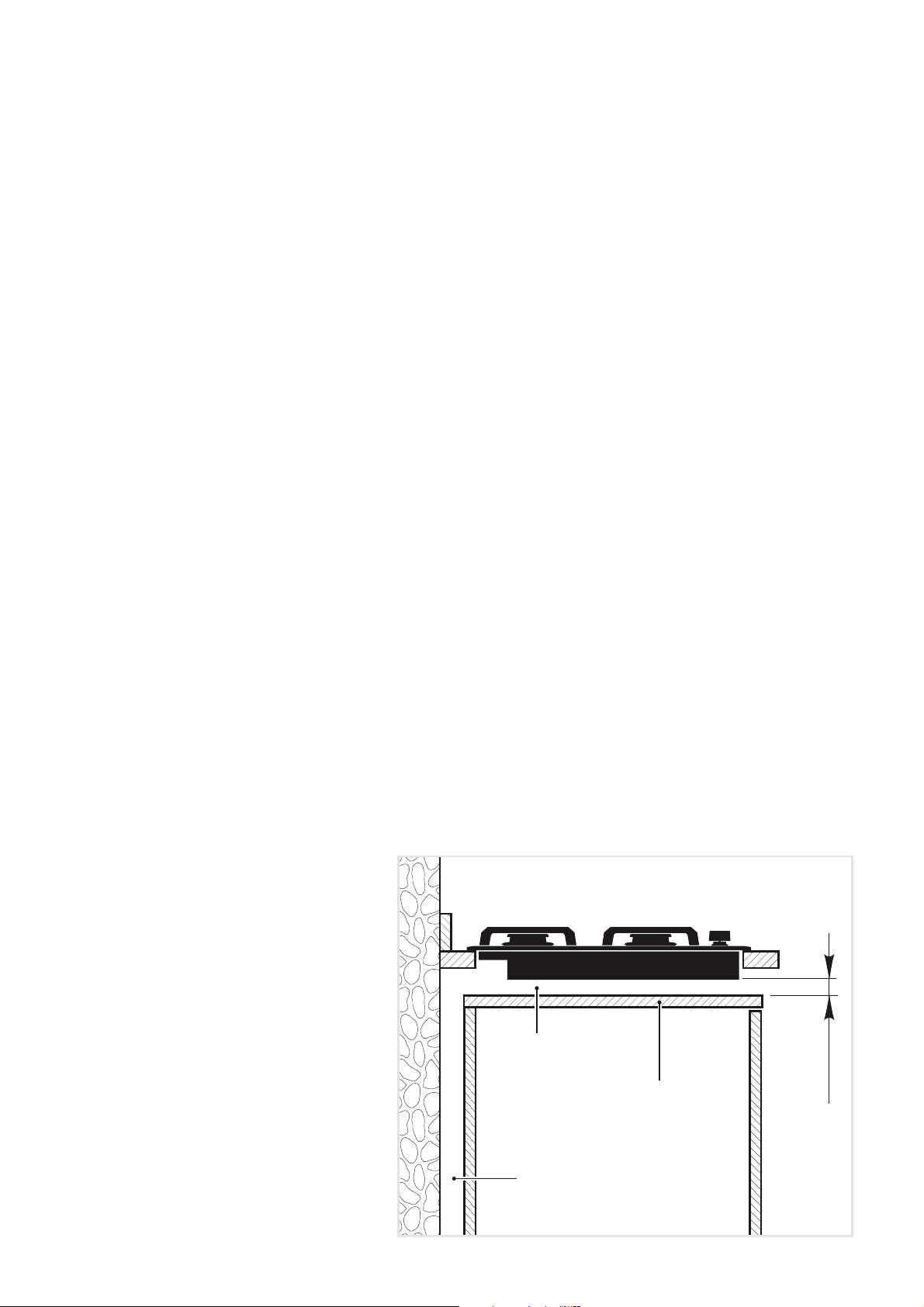
INSTALLING THE SEPARA-
TOR BELOW THE BASE OF
THE COOKTOP
It is recommended that a 30 mm
clearance be left between to base
of the cooktop and the separator.
The separator shall be heat resi-
stant, made of low thermal con-
ductivity material and shall be re-
movable with the use of a tool for
installation and service.
30 mm
Space for
connections
Clearance
Separator
Figure 5
Loading ...
Loading ...
Loading ...