Loading ...
Loading ...
Loading ...
Controlsmterminalconnections.
Controls-TerminalConnections
Tile texminal connections are located behind tile
front case panel through, an oi)ening, on tile
fl'ont of tile unit.
To access tile teFmillal COllllectiollS, remove tile
fl'ont panel by removing tile filtei, taking out tile
fimr fl'ont screws, tile upper two screws from tile
top ot the panel and the shipping screws on each
side, if present. (Discard the two side shipping
screws, if present).
Insert tile building hook-up wires into tile
bottom ol tile terminals and tighten screws
securely to make tile desired connections.
Route tile wires fl'om tile temfinal connections
through tile unit wire guides and out through
the case wire guide.
NO_.; The owner is responsible tot setting
tile appropriate dip switches and connecting
temfinals.
CAUTION:
hnproper CDC Mring may damage tile Zoneline Routewires
electronics or cause erratic Zoneline operation, through wire
No common busing is permitted. A separate wire guides
pair must be run fl'om each separate controlling
switch to each individual Zoneline,
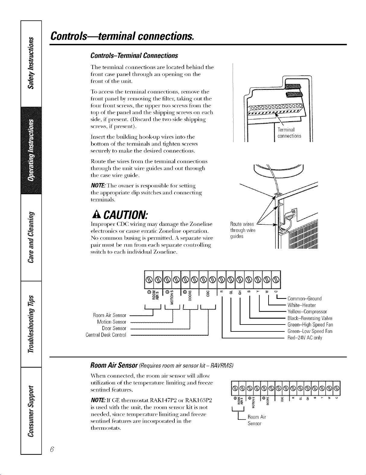
l H®l®l®i®l®i®l®l®l®l®l
RoomAirSensor
MotionSensor
DoorSensor
CentralDeskControl
o o [_ ommon-Ground
White-Heater
Yellow-Compressor
Black-Reversing Valve
Green-High Speed Fan
Green-Low Speed Fan
Red-24V AC only
Room Air Sensor (Requiresroomair sensorkit- RAVRMS)
"_._q/en connected, tile r(iom air sensor will alh)w
utilization of tile teinperature limiting and freeze
sentinel fb'atures.
NOTE: If GE them_ostat ]LM(147P2 or ILM(163P2
is used with tile unit, tile room sensor kit is not
needed, since temperature limiting and freeze
sentinel features are incoq)orated in tile
them_ostats.
o_ _ o
_:'* S= o
L Room Air
Sensor
Loading ...
Loading ...
Loading ...