Loading ...
Loading ...
Loading ...
Installation Instructions
[] iNSTALL THE DRAIN
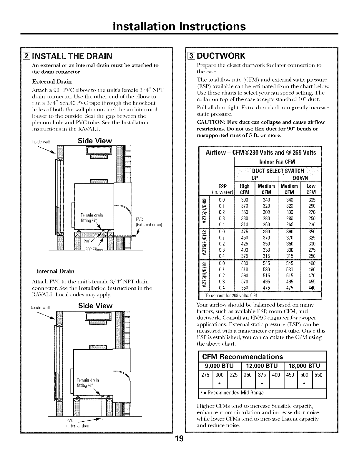
An externaJ or an internal drain must be attached to
the drain connector.
F_ternal Drain
Attach a 90 ° PVC elbow to the unit's fbmale 3/4" NPT
chain connecto_ Use the other end of the elbow to
run a 3/4" Sch.40 PVC pipe through the knockout
holes of both the wall plenum and the architectural
louver to the outside. Seal the gap between the
plenum hole and PVC tube. See the Installation
Instructions in the Ig_,VAL1.
Insidewall Side View
90° Elbow
iiiiiiiiiNIIN==
iiiiiiiiiJN==
iiiiiiiiiNIl_
HHHHi_
iiiiiiiiilllll===
HHHH_Ia_
PVC
(Externaldrain)
J
iiiiiiiIIm===
Internal Drain
Attach PVC to the unit's female '_ " )
.,/4 NIT drain
com_ector. See the Installation Instructions in the
IL_VAL1. Local codes ma)apply.
Insidewall Side View
PVC ....------"_J'_:'
(Internaldrain)
[] DUCTWORK
Prepare the closet ductwork for later com_ection to
the case.
The total flow rate (C[q¥1) and external static pressure
(ESP) ax:dlable can be estimated ti'om the chart below.
Use these charts to select your lira sl)eed setting. The
collar on top _ff the case accepts standard 10" duct.
Pull all duct tight. Extra duct slack can greatly increase
static pressure.
CAUTION: Flex duct can collapse mad cause airflow
restrictions. Do not use flex duct for 90 ° bends or
mlsupported rmls of 5 ft. or more.
19
Airflow - CFM@230 Volts and @ 265 Volts
indoor Fan CFM
swITc.
UP I DOWN
ESP High Medium Medium Low
(in.water) CFM CFM CFM CFM
0.0 390 340 340 305
0.1 370 320 320 290
0.2 350 300 300 270
0.3 330 280 280 250
'_ 0.4 310 260 260 230
0.0 475 390 390 350
0.1 450 370 370 325
0.2 425 350 350 300
Da 0.3 400 330 330 275
< 0.4 375 315 315 250
0.0 630 545 545 490
0.1 610 530 530 480
=: 0.2 590 515 515 470
Da 0.3 570 495 495 455
< 0.4 550 475 475 440
To correct for 208volts: 0.91
Your ai_low should be balanced based on many
fi_cto_, such as available ESP, room CFM, and
ductwork. Consult an HVAC engineer fi)r proper
applications. External static pressure (ESP) can be
measured with a manometer or pitot tube. Once this
ESP is established, you can calculate the CFM using
the above chart.
CFM Recommendations
= Recommended Mid Range
Higher CFMs tend to increase Sensible capadb;
enhance room circulation and increase duct noise,
while lower C[q¥1s tend to increase i,atent capacib'
and reduce noise.
Loading ...
Loading ...
Loading ...