Loading ...
Loading ...
Loading ...
Installation Instructions
DIRECT CONNECT APPLICATIONS
FOR 230/208 VOLT DIRECT
CONNECT APPLICATIONS ONLY
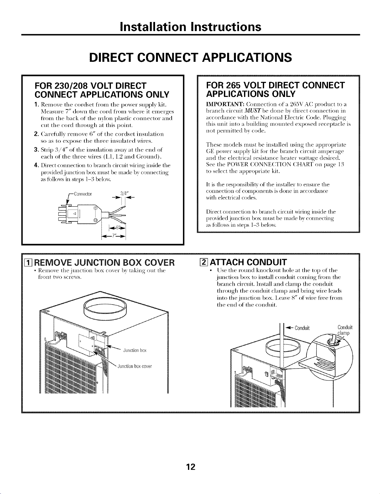
1. ]{emove the cordset fl'om the power supply kit.
Measure 7" down the cord fl'om where it emerges
fl'om the back of the nylon plastic connector and
cut the cord through at this point.
2. Careflfllv remove 6" of the cordset insulation
so as to expose the three insulated wires.
3. Strip 3/4" of the insulation away at the end of
each of the three wires (I,1, 1,9 and Ground).
4. Direct connection to branch circuit wiring inside the
provktedj unctkm box must be made b) connecting
as tbllo_:s in stops 1-3 below.
FOR 265 VOLT DIRECT CONNECT
APPLICATIONS ONLY
IMPORTANT: Connection of a 265V AC product to a
branch circuit MUST be done b) direct connection in
accordance with the Natkmal Electric Code. Plugging
this unit into a building mounted exposed receptacle is
not permitted b} code.
These models must be installed using the ai/propriate
GE power suppl? kit tot tile branch circuit amperage
and the electrical resistance heater wattage desired.
See the POWER CONNECTION (:HART on page 13
to select the al/propriate kit.
It is tile responsibilit) of tile installer to ensure tile
connection of con-}ponents is done ill accordance
with electrical codes.
Direct connection to branch circuit wiring inside the
proxidedjtmction box must be made b) connecting
as fi)llows in steps 1-,, beloxa
[] REMOVE JUNCTION BOX COVER
• Remo_e the junction box co_,er b) taking out the
t]'ont two screws.
[] ATTACH CONDUIT
• /_)se the round knockout hole at the toil of the
junction box to install conduit coming fl'om the
branch circuit. Install and clamp the conduit
through the conduit clamp and bring wire leads
into the j unction box. i,eave 8" ot wire fl'ee fl'om
the end of the conduit.
boxcover
Conduit Conduit
12
Loading ...
Loading ...
Loading ...