Loading ...
Loading ...
Loading ...
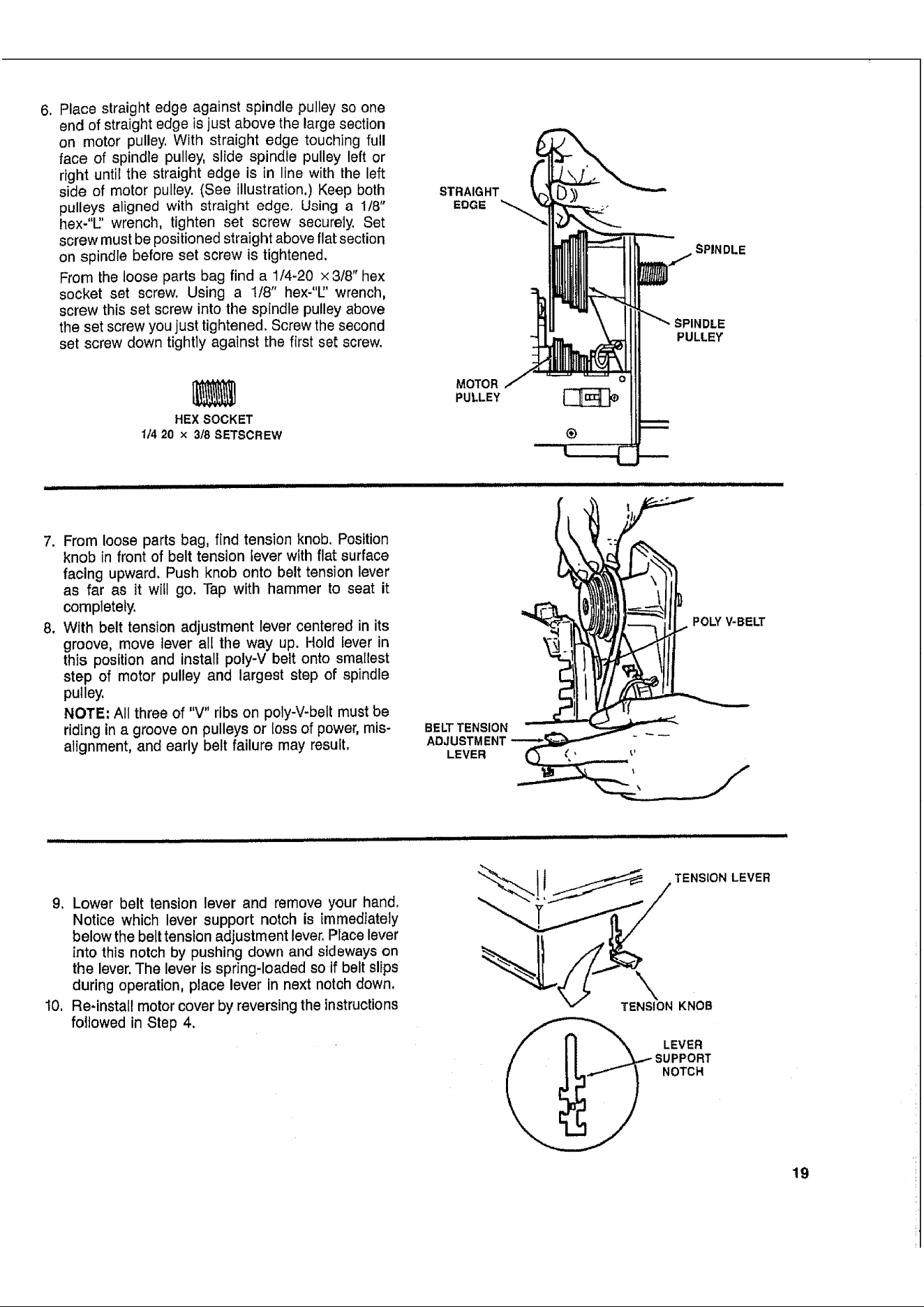
6. Placestraightedgeagainstspindlepulleysoone
endofstraightedgeisjustabovethelargesection
on motorpulley.Withstraightedgetouchingfull
faceofspindlepulley,slidespindlepulleyleftor
rightuntilthestraightedgeisin linewiththeleft
sideofmotorpulley,(Seeillustration,)Keepboth
pulleysalignedwithstraightedge,Usinga 118"
hex-"l"wrench,tightenset screwsecurely.Set
screwmustbepositionedstraightaboveflatsection
onspindlebeforesetscrewistightened.
Fromtheloosepartsbagfinda 1/4-20x3/8"he×
socketsetscrew.Usinga 1/8"hex-"U'wrench,
screwthissetscrewintothespindlepulleyabove
thesetscrewyoujusttightened.Screwthesecond
setscrewdowntightlyagainstthefirstsetscrew.
STRAIG HT
EDGE
SPINDLE
PULLEY
HEX SOCKET
1/4 20 x 318 SETSCREW
MOTOR
PULLEY
®
L iiii,1111 i i iiii i iiiiiiiiiiiiiiiiiiiilU
7. From loose parts bag, find tension knob. Position
knob in front of belt tension lever with flat surface
facing upward. Push knob onto belt tension lever
as far as it will go. Tap with hammer to seat it
completely.
8. With belt tension adjustment lever centered in its
groove, move lever all the way up. Hold lever in
this position and install poly-V belt onto smallest
step of motor pulley and largest step of spindle
pulley.
NOTE: All three of "V" ribs on poly-V-bett must be
riding in a groove on pulleys or loss of power, mis-
alignment, and early belt failure may result.
BELT TENSION
ADJUSTMENT
LEVER
POLY V-BELT
9. Lower belt tension lever and remove your hand.
Notice which lever support notch is immediately
below the belt tension adjustment lever. Place lever
into this notch by pushing down and sideways on
the lever. The lever is spring-loaded so if belt slips
during operation, place lever in next notch down.
10. Re-install motor cover by reversing the instructions
foltowed in Step 4.
iJllll IIBII I
TENSION LEVER
\
TENSION KNOB
SUPPORT
NOTCH
19
Loading ...
Loading ...
Loading ...