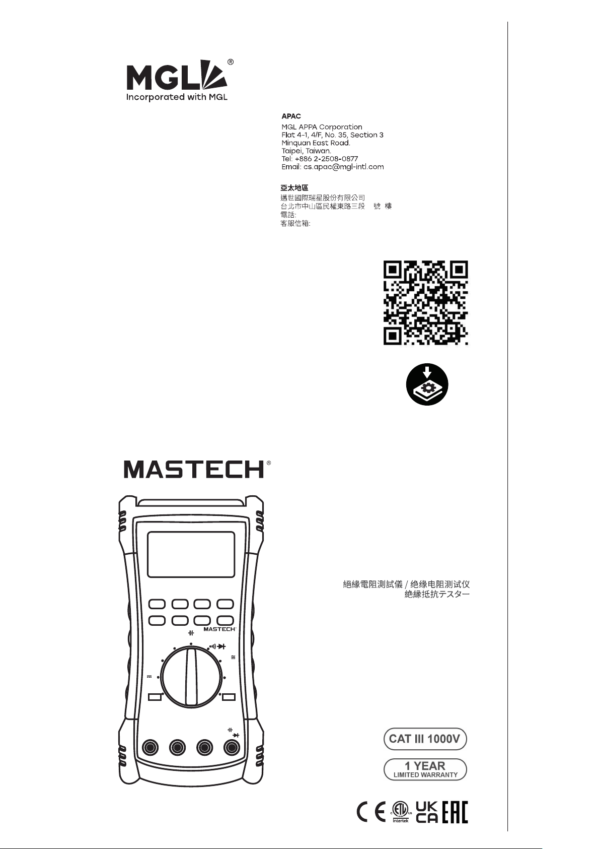
DIGITAL INSULATION TESTER
USER’SMANUAL

3.7 DAR&PI
3.8 Insulation Test Lock
3.9 Timer Function forinsulation
3.10 DataRecording
1.SAFETY INFORMATION
1.1 Warning
1.2 Warranty
1.3 Symbols
........................................01
.........................................................01
........................................................02
........................................................02
2.INTRODUCTION
...................................................03
2.1 Front Panel
2.2 Display Screen
2.3 Display Messages
2.4 Buttons
2.5 Rotary Switch
2.6 Input Terminal
.....................................................03
...............................................04
...........................................06
..........................................................07
.................................................08
................................................10
3.FUNCTION DESCRIPTION
....................................11
3.1 Power-Up Options
3.2 Automatic Power Off
3.3 Fully loaded battery test
3.4 Hold Function
3.5 Relative Measurement
3.6 Manual Ranging and Autoranging
..........................................11
.......................................11
..................................12
.................................................12
....................................12
....................12
.........................................................12
........................................13
............................13
4.MAKING BASIC MEASUREMENTS
........................19
............................................15
4.1 Measuring DC Voltage
4.2 Measuring AC Voltage
4.3 Measuring Temperature
.....................................19
.....................................20
..................................23
.............................25
............................29
.......................................31
4.4 Measuring Resistance
and Measuring Capacitance
4.6 Measuring AC or DC Current
4.7 Measuring frequency
4.8 InsulationTest
4.5 Measuring Continuity
and Measuring Diode
.......................................27
..............................................33
7.REPLACING BATTERY AND FUSE
........................39
5.GENERAL SPECIFICATIONS
................................36
6. ACCRUACY
........................................................37
8.ACCESSORIES
....................................................40
01
02
1. INTRODUCTION
This style of digital multimeter is designed and
manufactured according to the safety requirements set
out by EN61010-1, EN61010-2-030 standards for
electronic test instruments. Its design and manufacture is
strictly based on the provisions in the 1000V CAT III, 600V
CAT IV of IEC61010-1 and the Stipulation of 2-Pollution
Grade.
1.1 Warning
To avoid possible electric shock or personal injury, follow
these guidelines:
Use the Meter only as specified in this manual or the
protection provided by the Meter might be impaired.
Do not use the Meter or test leads if they appear
damaged, or if the Meter is not operating properly. If in
doubt, have the Meter serviced.
Always use the proper terminal, switch position, and
range for measurements before connecting Meter to
circuit under test.
Verify the Meter’s operation by measuring a known
voltage.
Do not apply more than the rated voltage as marked on
the Meter, between the terminals or between any
terminal and earth ground.
Use caution with voltages above 30 V ac rms, 42 V ac
peak, or 60 V dc. These voltages pose a shock hazard.
Replace the battery as soon as the low battery indicator
( ) appears.
Disconnect circuit power and discharge all high-voltage
capacitors before testing resistance, continuity, diodes,
or capacitance.
Do not use the Meter around explosive gas or vapor.
When using the test leads, keep your fingers behind the
finger guards.
Remove test leads from the Meter before opening the
Meter case or battery door.
Never operate the Meter with the cover removed or the
battery door open.
Comply with local and national safety requirements
when working in hazardous locations.
Use proper protective equipment, as required by local or
national authorities when working in hazardous areas.
Use only the replacement fuse specified or the protection
may be impaired.
If the meter is dirty after usage, it is advised to clean it by
using a humid cloth and mild house hold detergents.
Never use acid detergent or dissolvants.
1.2 Warranty
The meter is warranted to be free from defects in material
and workmanship under normal use and service. The
warranty period is one year and begins on the date of
shipment. Parts, product repairs, and services are
warranted for 18 months except for misused, altered,
neglected, contaminated, or damaged by accident or
abnormal conditions of operation or handling.This
warranty does not apply to fuses, disposable batteries.
1.3 Symbols
03
04
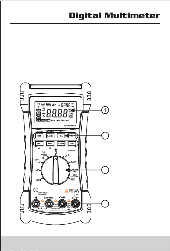
2.INTRODUCTION
This meter is a Digital Insulation Multimeter with broad
range of measurement, which can be used to measure DC
voltage, AC voltagem, current, AC current, resistance,
capacitance, frequency and temperature.
DIGITAL INSULATION TESTER
2.1 Front Panel
2
3
4
Screen
Buttons
RotarySwitch
Input Terminals
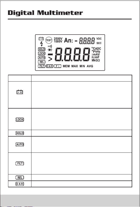
2.2 Display Screen
Indicator
Description
Low battery Indicates when it is time to
replace the battery. To avoid false readings,
which could lead to possible electric shock
or personal injury, replace the battery as
soon as the low battery indicator appears.
Indicates a test lock will be applied the next
time you press Test Button on the meter, the
test lock acts to hold down the button until
you press Test Button again.
Hold function, the meter do not update display.
In multimeters function,Indicating the meter
working in autorange function,else the meter
work in manual range mode.
Filter: when the rotary switch at ~V Position,
the meter active 1KHz low passed filter;
when the rotary switch at Insultation position,
the meter active Smoothing function.
Relatvive function.
In insulation test mode, display the DAR value.
03
04
2.INTRODUCTION
This meter is a Digital Insulation Multimeter with broad
range of measurement, which can be used to measure DC
voltage, AC voltagem, current, AC current, resistance,
capacitance, frequency and temperature.
DIGITAL INSULATION TESTER
2.1 Front Panel
2
3
4
Screen
Buttons
RotarySwitch
Input Terminals
2.2 Display Screen
Indicator
Description
Low battery Indicates when it is time to
replace the battery. To avoid false readings,
which could lead to possible electric shock
or personal injury, replace the battery as
soon as the low battery indicator appears.
Indicates a test lock will be applied the next
time you press Test Button on the meter, the
test lock acts to hold down the button until
you press Test Button again.
Hold function, the meter do not update display.
In multimeters function,Indicating the meter
working in autorange function,else the meter
work in manual range mode.
Filter: when the rotary switch at ~V Position,
the meter active 1KHz low passed filter;
when the rotary switch at Insultation position,
the meter active Smoothing function.
Relatvive function.
In insulation test mode, display the DAR value.
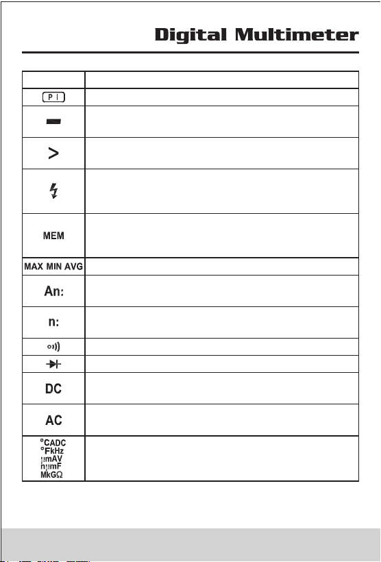
Indicator
Description
In insulation test mode, display the PI value.
Minus, When the measure value lower than 0,
display the sign.
Greater symbols, In insulation test mode,
indicates the measure value overflow.
Unsafe voltage warning, In insulation mode,
indicates greater 20V voltage is detected on
the input terminals.
Indicates the meter working in Record mode,
in this mode,meter can record the last 100
measure value
Display the Max, Min Avg value.
In Record mode, indicates the counts of the
recorded value
Display the sequence number of the recorded
value
Continuity test function is selected
Diode test function is selected
DC Voltage or DC Current test function is
selected
AC Voltage or AC Current test function is
selected
Measurements Units
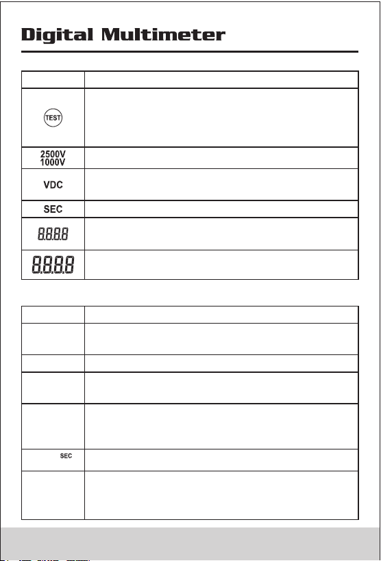
Indicator
Description
Source voltage rating for insulation test
Insulation Measuring time Unit
Auxiliary Display :display the output voltage,
time.
Primary Display: display the measure value
Insulation test Indicator.when the rotary
switch at insulation position, this sign appers,
when the test voltage is present ,the sign
alternate on or off
The measuring uint of source voltage rating
for insulation test
2.3 Display Messages
Indicator
Description
The auto power off function is not actived
Appears on Auxiliary display, Indicates the
battery too low to perform Insulation test
In insulation mode,indicates the meter
performs the auto discharge function; not to
touch any input terminals in this mode.
bat
POFF
In insulation mode,indicates meter have
detected the voltage on the input terminals
LIVE
DISC
The Timer function is not actived
OFF
LEAD
Check the test leads in proper terminals,the
rotary switch at current or insulation position,
display the message
05 06
Indicator
Description
In insulation test mode, display the PI value.
Minus, When the measure value lower than 0,
display the sign.
Greater symbols, In insulation test mode,
indicates the measure value overflow.
Unsafe voltage warning, In insulation mode,
indicates greater 20V voltage is detected on
the input terminals.
Indicates the meter working in Record mode,
in this mode,meter can record the last 100
measure value
Display the Max, Min Avg value.
In Record mode, indicates the counts of the
recorded value
Display the sequence number of the recorded
value
Continuity test function is selected
Diode test function is selected
DC Voltage or DC Current test function is
selected
AC Voltage or AC Current test function is
selected
Measurements Units
Indicator
Description
Source voltage rating for insulation test
Insulation Measuring time Unit
Auxiliary Display :display the output voltage,
time.
Primary Display: display the measure value
Insulation test Indicator.when the rotary
switch at insulation position, this sign appers,
when the test voltage is present ,the sign
alternate on or off
The measuring uint of source voltage rating
for insulation test
2.3 Display Messages
Indicator
Description
The auto power off function is not actived
Appears on Auxiliary display, Indicates the
battery too low to perform Insulation test
In insulation mode,indicates the meter
performs the auto discharge function; not to
touch any input terminals in this mode.
bat
POFF
In insulation mode,indicates meter have
detected the voltage on the input terminals
LIVE
DISC
The Timer function is not actived
OFF
LEAD
Check the test leads in proper terminals,the
rotary switch at current or insulation position,
display the message
05 06
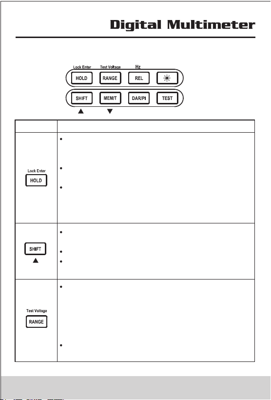
2.4 Buttons
Buttons
Description
When rotary switch at the position except
insulation, press the button, the display not
updated
When rotary switch at the insulation position,
press the button toggle the test lock
When rotary switch at the insulation position,
and the meter in set measure time mode,
press the button to save measure time and
exit set-measure time mode
Shift:press this button to active the function
higher rotary switch
In Record mode,function as page up
In Set-Measureing time mode,Increase the
assign value
When rotary switch at the position except
insulation:press this button ,the meter will
switch auto range
to manual range. Press this button longer
than 1S,the meter will switch manual range
to autorange.
When rotary switch at the insulation position,
select a source voltage for Test.
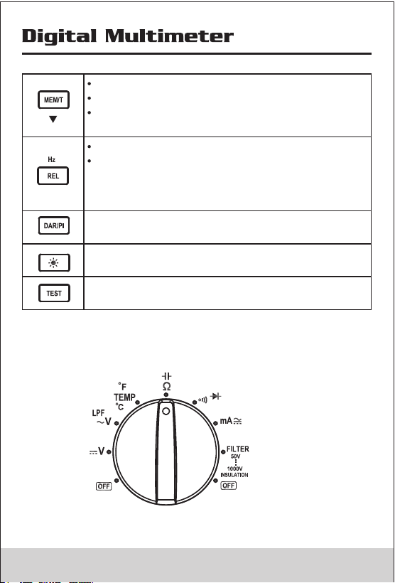
Actived the record function
In Record mode,function as page down
Actived the time function(When rotary
switch at the insulation position)
Actived relative function
Active the frequency measure function when
rotary switch at AC voltage;press the button
longer than 1S to perform the frequency
measurement
Display DAR or PI Value
Back Light on/Off,when the light turn on ,after
10S the meter auto turn off light
When rotary switch at the insulation position,
press the button to perform insulation test
2.5 Rotary Switch
07 08
2.4 Buttons
Buttons
Description
When rotary switch at the position except
insulation, press the button, the display not
updated
When rotary switch at the insulation position,
press the button toggle the test lock
When rotary switch at the insulation position,
and the meter in set measure time mode,
press the button to save measure time and
exit set-measure time mode
Shift:press this button to active the function
higher rotary switch
In Record mode,function as page up
In Set-Measureing time mode,Increase the
assign value
When rotary switch at the position except
insulation:press this button ,the meter will
switch auto range
to manual range. Press this button longer
than 1S,the meter will switch manual range
to autorange.
When rotary switch at the insulation position,
select a source voltage for Test.
Actived the record function
In Record mode,function as page down
Actived the time function(When rotary
switch at the insulation position)
Actived relative function
Active the frequency measure function when
rotary switch at AC voltage;press the button
longer than 1S to perform the frequency
measurement
Display DAR or PI Value
Back Light on/Off,when the light turn on ,after
10S the meter auto turn off light
When rotary switch at the insulation position,
press the button to perform insulation test
2.5 Rotary Switch
07 08
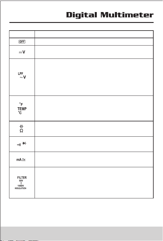
Position
Function
Turn off themeter power
DC Voltage 0.1mV~1000V (Note:mV Range
only exist in manual range)
1:AC Voltage 30mV~750V(note:mV Range
only exist in manual range)
2:Actived 1KHz low passed filter for AC
voltage(do not use the Low-Pass Filter
function to verify the presence of
hazardous voltages)
Celsius is the default temperature
measurement unit press shift button switch to
Fahrenheit measurement unit Temperature
from-30°C to1300°C (-22°F~2372°F)
Ohms : 0.1Ω~60MΩ
Capacitance: 0.01nF~60mF
Continuity
Diode
DC Current (0.01mA~400mA)
AC Current(3.00mA~400mA)
1:Insulation Test 0.01MΩ~2.0GΩ, Test
output Voltage 50V(default)、100V、
250V、500V、1000V, the test output
volatage have selected will be saved .
2:Digit filter function for Insulation test.
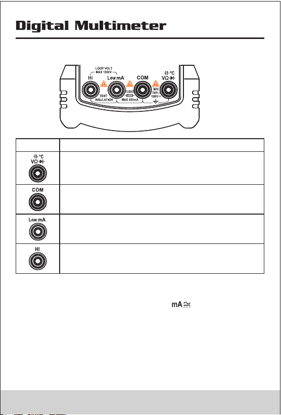
2.6 Input Terminal
Terminal
Description
Input positive terminal except current and
inuslation measure
Common terminal except Inuslation measure
Input positive terminal for current measure,do
not measure any current exceed 400mA
(TRMS)
Input positive terminal for Insulation measure
Note 1:To remind you to check that the test leads are in
the correct terminals, LEAd is momentarily displayed
when you move the rotary switch to or Insulation
Position
Warning
To avoid a blown fuse, damage to the Meter,or serious
personal injury, never attempt to make a measurement
with a test lead in an incorrect terminal.
09 10
Position
Function
Turn off themeter power
DC Voltage 0.1mV~1000V (Note:mV Range
only exist in manual range)
1:AC Voltage 30mV~750V(note:mV Range
only exist in manual range)
2:Actived 1KHz low passed filter for AC
voltage(do not use the Low-Pass Filter
function to verify the presence of
hazardous voltages)
Celsius is the default temperature
measurement unit press shift button switch to
Fahrenheit measurement unit Temperature
from-30°C to1300°C (-22°F~2372°F)
Ohms : 0.1Ω~60MΩ
Capacitance: 0.01nF~60mF
Continuity
Diode
DC Current (0.01mA~400mA)
AC Current(3.00mA~400mA)
1:Insulation Test 0.01MΩ~2.0GΩ, Test
output Voltage 50V(default)、100V、
250V、500V、1000V, the test output
volatage have selected will be saved .
2:Digit filter function for Insulation test.
2.6 Input Terminal
Terminal
Description
Input positive terminal except current and
inuslation measure
Common terminal except Inuslation measure
Input positive terminal for current measure,do
not measure any current exceed 400mA
(TRMS)
Input positive terminal for Insulation measure
Note 1:To remind you to check that the test leads are in
the correct terminals, LEAd is momentarily displayed
when you move the rotary switch to or Insulation
Position
Warning
To avoid a blown fuse, damage to the Meter,or serious
personal injury, never attempt to make a measurement
with a test lead in an incorrect terminal.
09 10
3. Function Description
3.1 Power-UP Option
Holding a button down while turning the Meter on activates
a power-up option. Power-up options allow you to use
additional features and functions of the Meter. To select a
power-up option, hold down the appropriate button
indicated while turning the Meter from OFF to any switch
position. Power-up options are cancelled when the Meter
is turned OFF
Buttons Function
SHIFT Turns on all LCD segments.
MEM Disables automatic power-off function
Display shows PoFF until the button is
released
TEST Disable the timer of insulation function
DAR/PI Initiates a fully loaded battery test and
displays the charge level of the battery
until the button is released.
3.2 Automatic Power OFF
The Meter have automatic power off function(Sleep mode)
to conserve battery power .if there is no function change or
button press for 10 minutes. The Meter comes out of Sleep
mode when a key is pressed or when the rotary switched is
changed.
To disable the Sleep mode, hold down MEM button while
turning the Meter on. Sleep mode is always disabled in the
recording mode, insulation test active, or if the auto power
off feature has been disabled by pressing MEM button
when the Meter is turned on.
3.3 Fully loaded battery test
Hold down DAR/PI button while turning the Meter on,the
meter display the battery voltage.
Put up the DAR/PI button to exit battery voltage test.
3.4 Hold Funcion(rotary switch at the position except
insulation)
Press Hold button to freeze the displayed value. Press
again to release the display.
3.5 Relative Measurement
Show the difference between actual value and the relative
base.
Press REL Button to enter relative measurement and the
meter will record the initial value when pressing the key.
Displayed value = Actual value -Initial value
Press REL Button again to exit relative measurement.
3.6 Manual Ranging and Autoranging
To enter the Manual Range mode, press Range button and
Auto is hide, In the Manual Range mode, press Range
button to increment the range. After the highest range, the
Meter wraps to the lowest range.
To exit Manual Range, press Range button for one second
or turn the rotary switch. The Meter returns to Autorange
and Auto is displayed.
3.7 DAR and PI
Sometimes an insulation part with obvious drawbacks
(e.g., the insulation part is broken through under high
voltage) is nevertheless with a good absorption ratio (or
polarization index). Therefore, absorption ratio
(polarization index) cannot be used to discover local
insulation drawbacks other than dampness and
contamination.
DAR and PI

DAR(absorbing ratio)=
R 60 Sec
R 15 Sec
PI(polarization index)=
R 10 Min
R 1 Min
R10Min= Resistance value measured 10 minutes after
applying the test voltage; R1Min=R60Sec= Resistance
value measured 10 minutes after applying the test voltage;
R15Sec= Resistance value measured 10 minutes after
applying the test voltage After performed insulation test,
press DAR/PI button, meter display DAR; press DAR/PI
button again, meter display PI. If DAR
or PIValue invalid, themeter display - - - - .
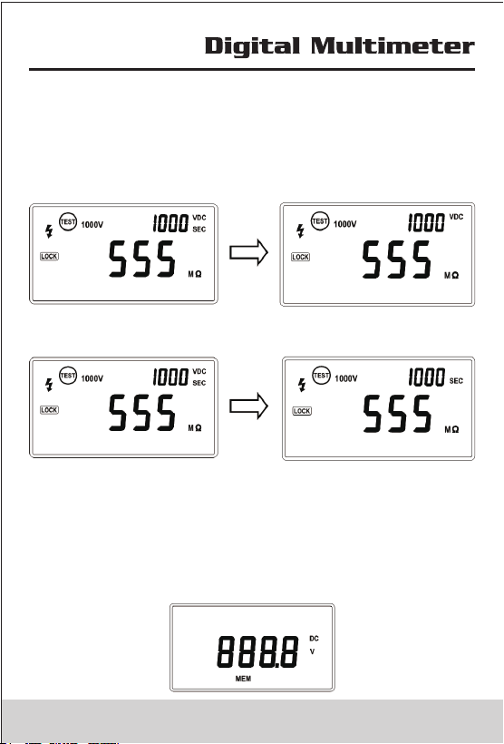
3.8 Insulation Test Lock
In insulation test mode, press Test button to perform
insulation test until the button is released.when the button
is released,the screen display hold sign.
Press Lock Button ,then the screen display Lock sign,
press Test Button ,the meter will perform insulation test
unitl you press Test button again;The test lock will
unlocked while to cancel insulation test.
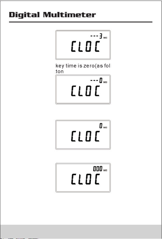
3.9 Timer Function for insulation
• Timer function is only valid in insulation test.
• In Init-Insulation status(Init-Insulation status is the
rotary switch to Insulation position or have performed
insulation test), press MEM button longer than 2S, the
secondary screen display the remain key time,and
primary screen display the ‘CLOC’
• When the remain key time is zero(as follow figure),
Release MEM button
• The meter enter timer set-up status, the secondary
screen display the preset time
• Press MEM button to change positon, press shift button
to change value
• Press HOLD button will save measuring time,and exit the
assign status.
• When the measureing time is greater than zero and the
test lock is unlocked,meter will activate the timer function,
the meter will be automatically stop the test when the
13 14
DAR(absorbing ratio)=
R 60 Sec
R 15 Sec
PI(polarization index)=
R 10 Min
R 1 Min
R10Min= Resistance value measured 10 minutes after
applying the test voltage; R1Min=R60Sec= Resistance
value measured 10 minutes after applying the test voltage;
R15Sec= Resistance value measured 10 minutes after
applying the test voltage After performed insulation test,
press DAR/PI button, meter display DAR; press DAR/PI
button again, meter display PI. If DAR
or PIValue invalid, themeter display - - - - .
3.8 Insulation Test Lock
In insulation test mode, press Test button to perform
insulation test until the button is released.when the button
is released,the screen display hold sign.
Press Lock Button ,then the screen display Lock sign,
press Test Button ,the meter will perform insulation test
unitl you press Test button again;The test lock will
unlocked while to cancel insulation test.
3.9 Timer Function for insulation
• Timer function is only valid in insulation test.
• In Init-Insulation status(Init-Insulation status is the
rotary switch to Insulation position or have performed
insulation test), press MEM button longer than 2S, the
secondary screen display the remain key time,and
primary screen display the ‘CLOC’
• When the remain key time is zero(as follow figure),
Release MEM button
• The meter enter timer set-up status, the secondary
screen display the preset time
• Press MEM button to change positon, press shift button
to change value
• Press HOLD button will save measuring time,and exit the
assign status.
• When the measureing time is greater than zero and the
test lock is unlocked,meter will activate the timer function,
the meter will be automatically stop the test when the
13 14
time is longer than preset time.
Note: Press Test button and turn on the meter,the meter
display and the timer function will be invalid..
• When the timer function is active,secondary screen
display the output volatage,and alternately turn on or
off ’ SEC’
OFF
SEC
• Press shift button ,the secondary screen display the
measuring time and alternately turn on or off ’VDC’
• Press test button to stop insulation test.
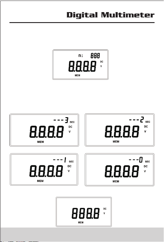
3.10 Data Recording
Data Recording in multimeter mode
• Press MEM button to enter recording status, the meter
display ‘MEM’ as follows:In recording status,meter record
the measuring value(when the record exceed 100
counts,the meter only record the last 100 counts).
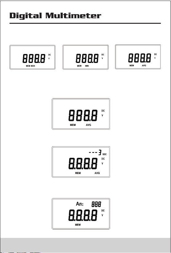
• In recording status,press MEM button in succession, the
meter will display the Max value,Min value, and Avg value.
• In recording status (or when the meter display Max、Min
value ),press MEM button longer than 1S,the meter will
exit recording status.
• When meter display avg value as follows:
• Press MEM button longer than 1S ,the secondary screen
display the remain key time .
• When the remain key time is zero ,the secondary screen
display the counts of the recorded value as follows
15 16
time is longer than preset time.
Note: Press Test button and turn on the meter,the meter
display and the timer function will be invalid..
• When the timer function is active,secondary screen
display the output volatage,and alternately turn on or
off ’ SEC’
OFF
SEC
• Press shift button ,the secondary screen display the
measuring time and alternately turn on or off ’VDC’
• Press test button to stop insulation test.
3.10 Data Recording
Data Recording in multimeter mode
• Press MEM button to enter recording status, the meter
display ‘MEM’ as follows:In recording status,meter record
the measuring value(when the record exceed 100
counts,the meter only record the last 100 counts).
• In recording status,press MEM button in succession, the
meter will display the Max value,Min value, and Avg value.
• In recording status (or when the meter display Max、Min
value ),press MEM button longer than 1S,the meter will
exit recording status.
• When meter display avg value as follows:
• Press MEM button longer than 1S ,the secondary screen
display the remain key time .
• When the remain key time is zero ,the secondary screen
display the counts of the recorded value as follows
15 16
• Press MEM button ,the secondary screen display the
sequence number of the recorded value and the Primary
display corresponding value.
• Press MEM button to page down,and press Shift button
to page up; press MEM button longer than 1S,then the
secondary screen display the key remain time.when the
key remain time is zero,the meter will be back to Record
status.
• When the key remain time is zero,the meter will be back
to Record status.
• Data Recording in insulation test mode
• In insulation test mode, the recording function will be
activated, press MEM button to view the recorded value,
the detailed operation is the same as data-recording in
multimeter mode.
17 18
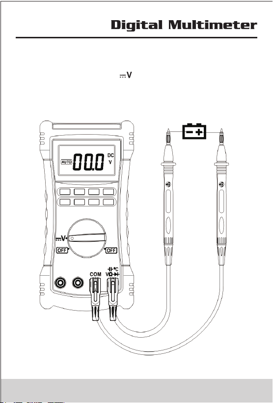
4. Making Basic Measurements
4.1 Measuring DC Voltage
• Switch rotary switch to Position, Input terminals and
test leads connecting as follows figure, then connet test
leads to circuit.
• mV Range in AutoRangeing is Invalid.
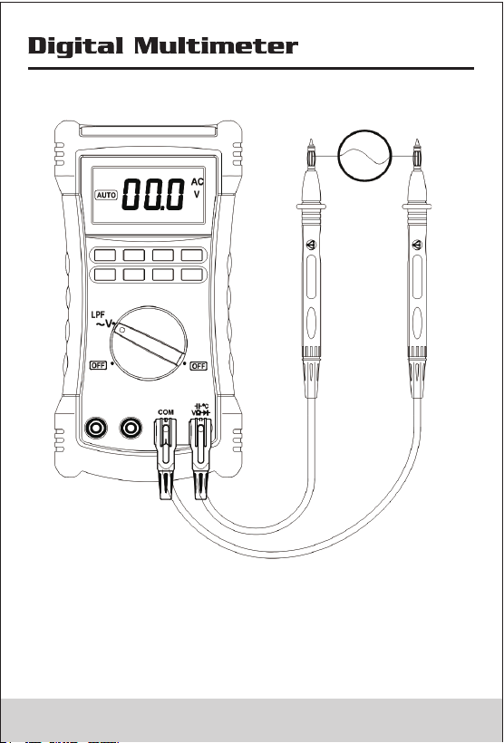
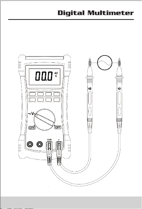
4.2 Measuring AC Voltage
19 20
4. Making Basic Measurements
4.1 Measuring DC Voltage
• Switch rotary switch to Position, Input terminals and
test leads connecting as follows figure, then connet test
leads to circuit.
• mV Range in AutoRangeing is Invalid.
4.2 Measuring AC Voltage
19 20
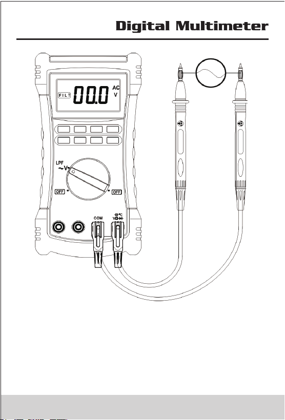
True RMS Meters accurately measure distorted
waveforms, but when the input leads are shorted together
in the AC functions, the Meter displays a residual reading
between 1 and 30 counts. When the test leads are open,
the display readings may fluctuate due to interference.
These offset readings are normal. They do not affect the
Meter’s ac measurement accuracy over the specified
measurement ranges.
In AC Voltage measuring Mode to actived Low passed filter,
the signal diverts through a filter that blocks unwanted
frequencies above 1K Hz. To actived this funtion ,press
shift button,the screen display , to cancel low passed
filter function ,press Shift button again ;
To avoid possible electric shock or personalinjury, do not
use the Low-Pass Filter function to verify the presence of
hazardous voltages. Voltages greater than what is
indicated may be present. First, make a voltage
measurement without the filter to detect the possible
presence of hazardous voltage. Then, select the filter
function
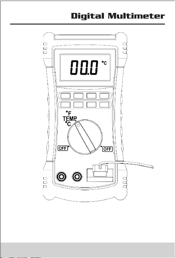
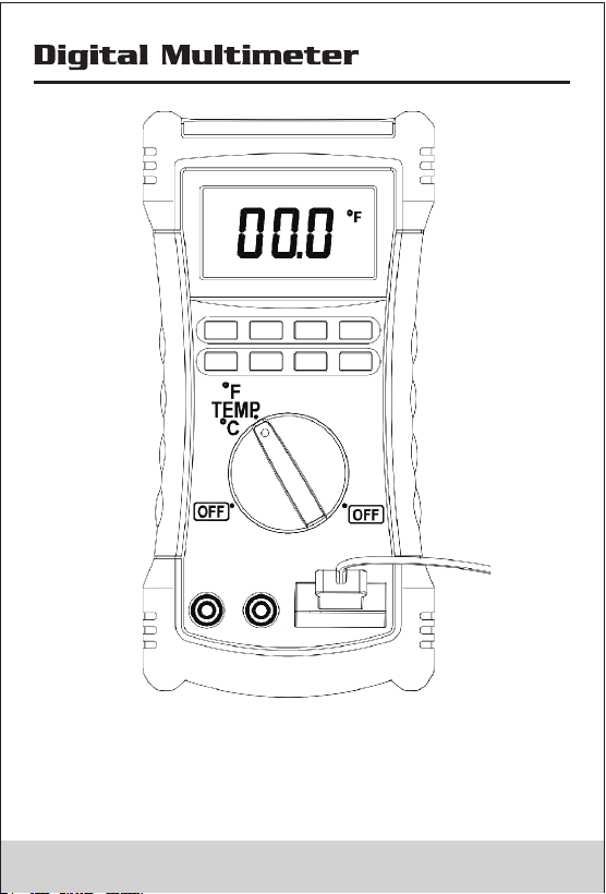
4.3 Measuring Temperature
The Meter measures the temperature of a type-K
thermocouple (included). Choose between degrees
Celsius (°C) or degrees Fahrenheit (°F) by pressing Shift
Button;
when the type-K thermocouple not connect to meter, the
meter display the ambient temperature the Meter is rated
for -30°C to 1300°C, the included K-type thermocouple is
rated for 260°C. For temperatures out of that range, use a
higher rated thermocouple.
To avoid risk of shock, do not connect thermocouple to
electrically live circuits.
21 22

True RMS Meters accurately measure distorted
waveforms, but when the input leads are shorted together
in the AC functions, the Meter displays a residual reading
between 1 and 30 counts. When the test leads are open,
the display readings may fluctuate due to interference.
These offset readings are normal. They do not affect the
Meter’s ac measurement accuracy over the specified
measurement ranges.
In AC Voltage measuring Mode to actived Low passed filter,
the signal diverts through a filter that blocks unwanted
frequencies above 1K Hz. To actived this funtion ,press
shift button,the screen display , to cancel low passed
filter function ,press Shift button again ;
To avoid possible electric shock or personalinjury, do not
use the Low-Pass Filter function to verify the presence of
hazardous voltages. Voltages greater than what is
indicated may be present. First, make a voltage
measurement without the filter to detect the possible
presence of hazardous voltage. Then, select the filter
function
4.3 Measuring Temperature
The Meter measures the temperature of a type-K
thermocouple (included). Choose between degrees
Celsius (°C) or degrees Fahrenheit (°F) by pressing Shift
Button;
when the type-K thermocouple not connect to meter, the
meter display the ambient temperature the Meter is rated
for -30°C to 1300°C, the included K-type thermocouple is
rated for 260°C. For temperatures out of that range, use a
higher rated thermocouple.
To avoid risk of shock, do not connect thermocouple to
electrically live circuits.
21 22
23 24
23 24
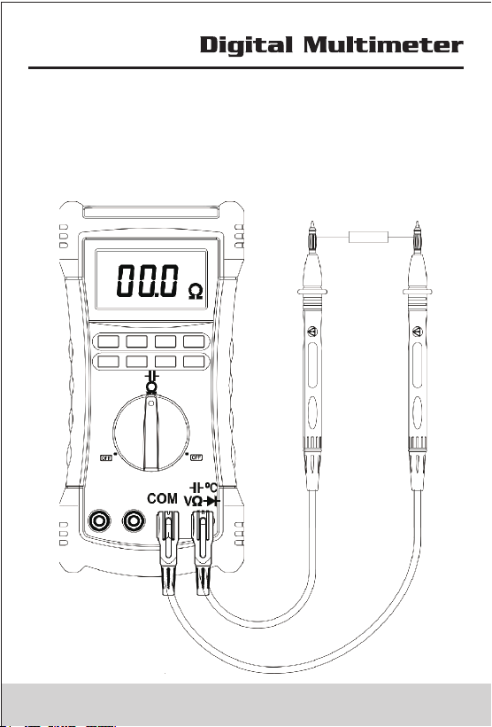
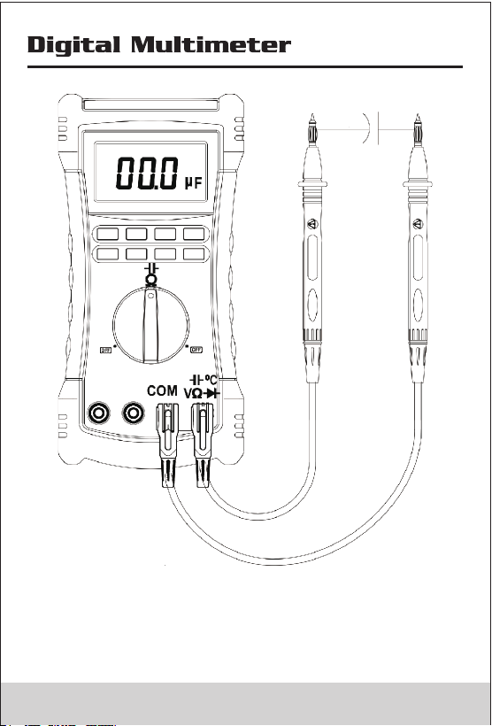
4.4 Measuring Resistance and Measuring Capacitance
To avoid possible damage to the Meter or to the equipment
under test, disconnect circuit power and discharge all high
voltage capacitors before testing for continuity.
Press Shift button switch between Measuring Resistance
and Measuring Capacitance
25 26
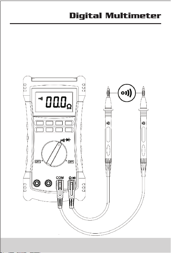
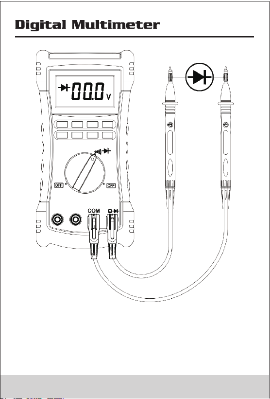
4.5 Measuring Continuity and Measuring Diode
The continuity test and diode test features a beeper that
sounds as long as a circuit is complete. The beeper
sounds when a short (<30 Ω)or forward voltage lower than
300mV.
Press Shift button switch between Measuring Continuity
and Measuring Diode.
27 28
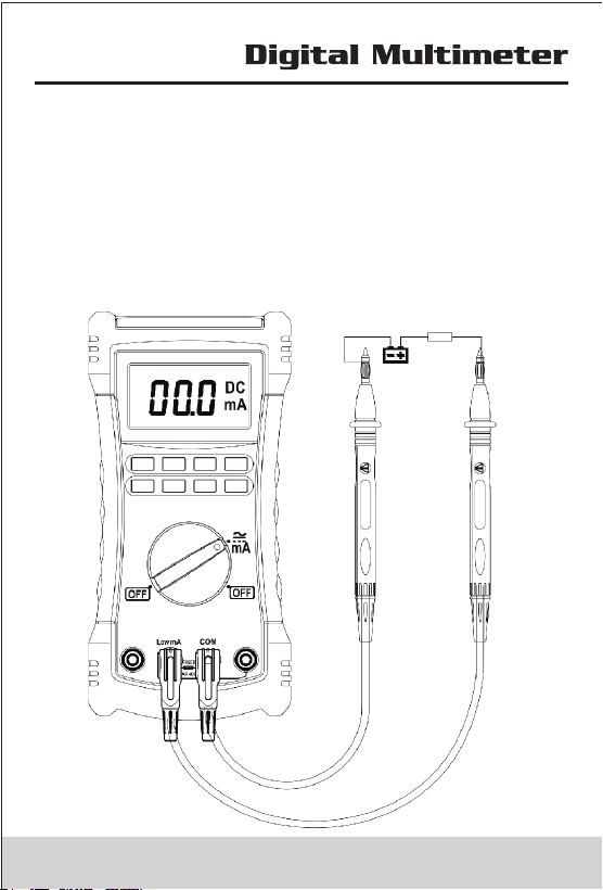
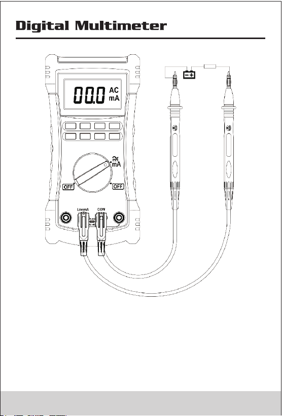
4.6 Measuring AC or DC Current
• Check fuse is good before Test;
• Select proper input terminal、rotary switch、range ; not
to measuring the current exceed the meter current rating
(400mA)
• Turn power OFF to the circuit under test, break circuit,
insert Meter in series,then turn power on
• Press Shift button switch between Measuring DC
Current and Measuring AC Current.
29 3 0
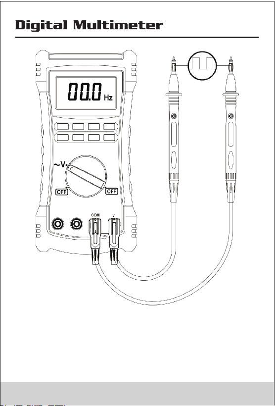
4.7 Measuring frequency
In Measuring AC Voltage mode, Press Hz button Longer
than 1S, the meter switch measuring voltage to frequency
In Frequency mode, the Range button is invalid. press Hz
button, the meter will switch to measuringAC Voltage.
31 32
4.7 Measuring frequency
In Measuring AC Voltage mode, Press Hz button Longer
than 1S, the meter switch measuring voltage to frequency
In Frequency mode, the Range button is invalid. press Hz
button, the meter will switch to measuringAC Voltage.
31 32
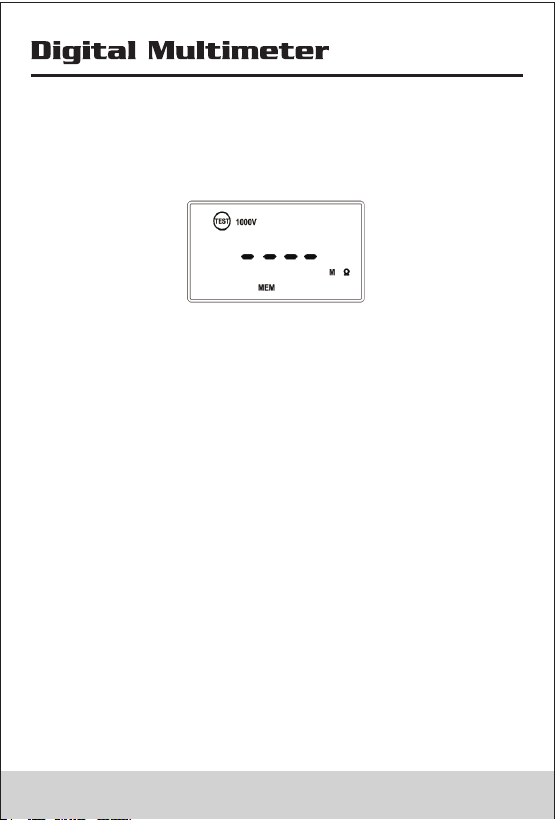
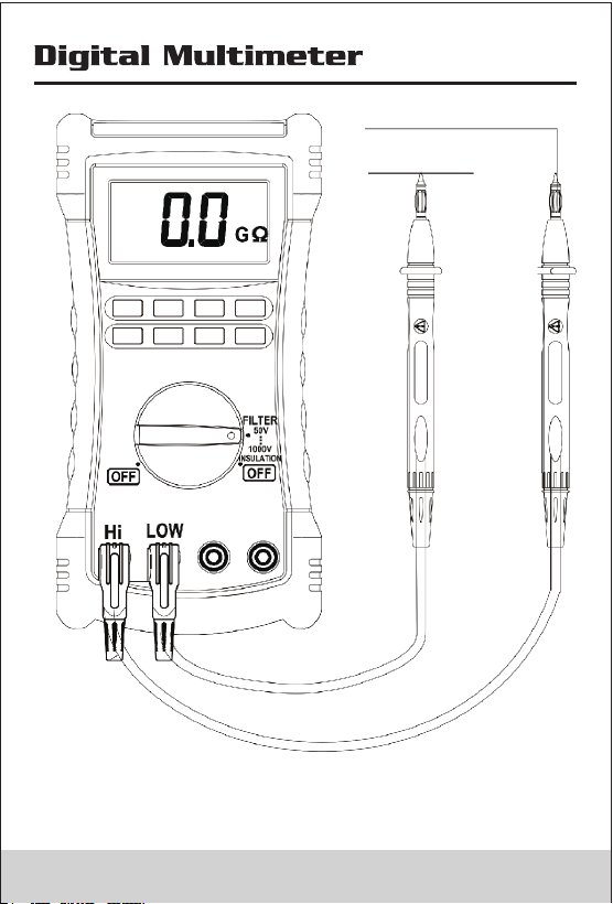
4.8 Insulation Test
• Insulation tests should only be performed on dead
circuits. Check the fuse and test leads before testing.
• Switch rotary to Insulation position. if meter display ,
please replease battery.
• Insert test leads to High/Low terminals. if the meter
display Live and , indicator the meter cannot measure
on live circuit.please power off Live circuit..
• Press Range button to select output voltage;
• Press test button to perform insulation test, when the
source voltage outputed the screen display .
• In insulation measuring ,the screen alternate turn on
or off, the primary screen display the resistance value,
and the secondary screen display the Output voltage.
Release the test button then discharges through the
Meter, the meter display DISC.
• The secondary Display 0 VDC indicator when the voltage
discharge finished.
• Disconnect the test leads from circuit..
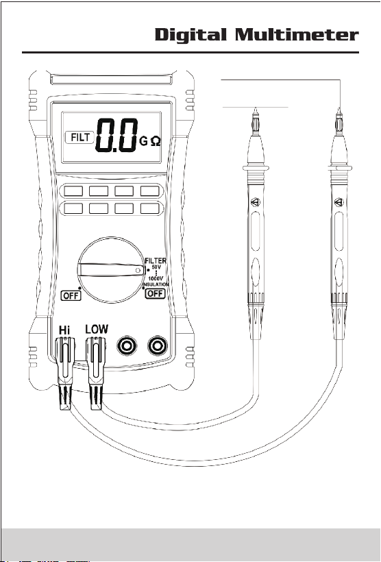
• Active smoothing funciton by press Shift button ,the
meter display .
33 34
4.8 Insulation Test
• Insulation tests should only be performed on dead
circuits. Check the fuse and test leads before testing.
• Switch rotary to Insulation position. if meter display ,
please replease battery.
• Insert test leads to High/Low terminals. if the meter
display Live and , indicator the meter cannot measure
on live circuit.please power off Live circuit..
• Press Range button to select output voltage;
• Press test button to perform insulation test, when the
source voltage outputed the screen display .
• In insulation measuring ,the screen alternate turn on
or off, the primary screen display the resistance value,
and the secondary screen display the Output voltage.
Release the test button then discharges through the
Meter, the meter display DISC.
• The secondary Display 0 VDC indicator when the voltage
discharge finished.
• Disconnect the test leads from circuit..
• Active smoothing funciton by press Shift button ,the
meter display .
33 34
5. General Specifications
Complies with IEC/EN 61010-1 1000V CAT III, •
600 V CAT IV.
• 1000V DC Voltage 750VAC Voltage TRMS ., ( )
• 6600 Count except for capacitance, temperature, (
insulation .)
• When the input terminals is V and COM, The overload
protective voltage is up to AC 250 V (TRMS) ; When the
input terminals is mA and COM, protective Current is
0.4A; when the input terminals is Hi and Lo, The overload
protective voltage is 600V.
• Batteries Four AA batteries (NEDA 15A or IEC LR6) :
Meter use 1000 hours; Insulation test use: Meter can
perform at least 1000 insulation tests with fresh alkaline
batteries at room temperature. These are standard tests
of 1000 V into 1 M with a duty cycle of 5 seconds on and Ω
25 seconds off.
• Insulation Measurement Range: 0.01 M to 2 G .Ω Ω
• Insulation Test Voltages: 50V, 100V, 250V, 500V, 1000V .
• Insulation Source Voltage: + 20%, - 0%.
• Insulation Short-Circuit Test Current : 1 .5mA nominal.
• Insulation Auto Discharge : Discharge time <1 second for
C = 1 F or less.μ
• Insulation Live Circuit Detection : Inhibit test if terminal
voltage > 20V prior to initialization of test.
• Insulation Maximum Capacitive Load: Operable with up
to 1μF load.
• Storage Temperature : -40 °C to 60 °C.
• Operating Temperature: 0°C to 40 °C .
• Storage Altitude: 12000m
• Operating Altitude: 2000m 1000V CAT III, 3000m 1000V
CAT II
• Temperature Coefficient: 0.05 × (specified accuracy) per
35 36
°C for temperatures < 18 °C or > 28 °C.
• Relative Humidity: 40%~75%.
• Size: 205(L)×102(W)× 58(H)mm.
• Weight: approx 390g.
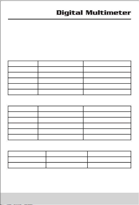
6. Accruacy
6.1 DC Voltage
Range Resolution Accuracy
660mV 0.1mV ±(0.5%+5)
6.6V 1mV ±(0.5%+5)
66V 10mV ±(0.5%+5)
660V 100mV ±(0.5%+5)
1000V 1V ±(0.5%+5)
6.2 AC Voltage
Range Resolution Accuracy
660mV 0.1mV --------
6.6V 1mV ±(1.5%+30)
66V 10mV ±(1.5%+30)
660V 100mV ±(1.5%+30)
750V 1V ±(1.5%+30)
6.3 Temperature
Range Resolution Accuracy
-30°C~1300°C 1°C ±(1.0%+2)
-22°F~2372°F 1°F ±(1.0%+4)
Accuracies apply following 90 minutes settling time after
a change in the ambient temperature of the instrument.
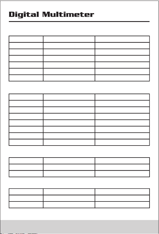
6.4 Resistance
Range Resolution Accuracy
660Ω 0.1Ω ±(1.2%+5)
6.6KΩ 1Ω ±(1.2%+5)
66KΩ 10Ω ±(1.2%+5)
660KΩ 100Ω ±(1.2%+5)
6.6MΩ 1KΩ ±(2.0%+20)
66MΩ 10KΩ ±(2.0%+20)
6.5 Capacitance
Range Resolution Accuracy
66nF 10pF ±(5.0%+20)
660nF 0.1nF ±(5.0%+20)
6.6μF 1nF ±(5.0%+20)
66μF 10nF ±(5.0%+20)
660μF 0.1μF ±(5.0%+20)
6.6mF 1μF ±(5.0%+20)
66mF 10μF ±(5.0%+20)
6.6 DC Current
Range Resolution Accuracy
66mA 0.01mA ±(1%+5)
400mA 0.1mA ±(1%+5)
6.7 AC Current
Range Resolution Accuracy
66mA 0.01mA ±(1.5%+30)
400mA 0.1mA ±(1.5%+30)
37 38
°C for temperatures < 18 °C or > 28 °C.
• Relative Humidity: 40%~75%.
• Size: 205(L)×102(W)× 58(H)mm.
• Weight: approx 390g.
6. Accruacy
6.1 DC Voltage
Range Resolution Accuracy
660mV 0.1mV ±(0.5%+5)
6.6V 1mV ±(0.5%+5)
66V 10mV ±(0.5%+5)
660V 100mV ±(0.5%+5)
1000V 1V ±(0.5%+5)
6.2 AC Voltage
Range Resolution Accuracy
660mV 0.1mV --------
6.6V 1mV ±(1.5%+30)
66V 10mV ±(1.5%+30)
660V 100mV ±(1.5%+30)
750V 1V ±(1.5%+30)
6.3 Temperature
Range Resolution Accuracy
-30°C~1300°C 1°C ±(1.0%+2)
-22°F~2372°F 1°F ±(1.0%+4)
Accuracies apply following 90 minutes settling time after
a change in the ambient temperature of the instrument.
6.4 Resistance
Range Resolution Accuracy
660Ω 0.1Ω ±(1.2%+5)
6.6KΩ 1Ω ±(1.2%+5)
66KΩ 10Ω ±(1.2%+5)
660KΩ 100Ω ±(1.2%+5)
6.6MΩ 1KΩ ±(2.0%+20)
66MΩ 10KΩ ±(2.0%+20)
6.5 Capacitance
Range Resolution Accuracy
66nF 10pF ±(5.0%+20)
660nF 0.1nF ±(5.0%+20)
6.6μF 1nF ±(5.0%+20)
66μF 10nF ±(5.0%+20)
660μF 0.1μF ±(5.0%+20)
6.6mF 1μF ±(5.0%+20)
66mF 10μF ±(5.0%+20)
6.6 DC Current
Range Resolution Accuracy
66mA 0.01mA ±(1%+5)
400mA 0.1mA ±(1%+5)
6.7 AC Current
Range Resolution Accuracy
66mA 0.01mA ±(1.5%+30)
400mA 0.1mA ±(1.5%+30)
37 38
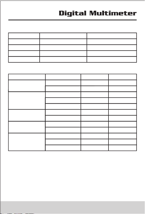
6.8 Frequency
Range Resolution Accuracy
660.0Hz 0.1Hz ±(1.5%+5)
6.600kHz 1Hz ±(1.5%+5)
66.00kHz 10Hz ±(1.5%+5)
>10kHz --------
6.9 Insulation
Output Voltage Display Range Resolution Accuracy
0~5MΩ 0.01MΩ ±(3%+5)
5~50MΩ 0.1MΩ ±(3%+5)
50V(0~20%)
0~5MΩ 0.01MΩ ±(3%+5)
5~50MΩ 0.1MΩ ±(3%+5)
50~100MΩ 1MΩ ±(3%+5)
100V(0~20%)
0~25MΩ 0.1MΩ ±(3%+5)
25~250MΩ 1MΩ ±(3%+5)
250V(0~20%)
0~50MΩ 0.1MΩ ±(3%+5)
50~500MΩ 1MΩ ±(3%+5)
500V(0~20%)
0~50MΩ 0.1MΩ ±(3%+5)
50~500MΩ 1MΩ ±(3%+5)
0.5G~2.0GΩ 0.1GΩ ±(5%+5)
1000V(0~20%)
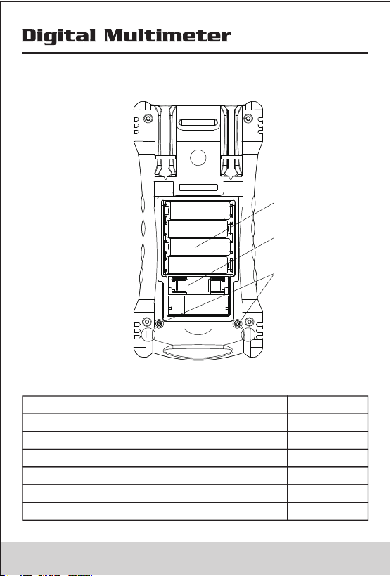
7. Replacing battery and fuse
• Only qualified service personnel are required to repair it.
• To avoid false readings, which could lead to possible
electric shock or personal injury, replace the batteries
(4 x 1.5V AA batteries) as soon as the battery indicator
appears.
• Use only fuses with the amperage interrupt voltage and
speed ratings specified (F 400mA, 1000V).
Battery
Fuse
Screw
• Turn the rotary switch to OFF and remove the test leads
from the terminals.
8. Accessories
Item
Quantity
Test Leads
Clips
K Type Thermocouple
Battery AA LR6
Manual
Multi-Function Socket
2
2
1
4
1
1
39
R-00-05-0292
6.8 Frequency
Range Resolution Accuracy
660.0Hz 0.1Hz ±(1.5%+5)
6.600kHz 1Hz ±(1.5%+5)
66.00kHz 10Hz ±(1.5%+5)
>10kHz --------
6.9 Insulation
Output Voltage Display Range Resolution Accuracy
0~5MΩ 0.01MΩ ±(3%+5)
5~50MΩ 0.1MΩ ±(3%+5)
50V(0~20%)
0~5MΩ 0.01MΩ ±(3%+5)
5~50MΩ 0.1MΩ ±(3%+5)
50~100MΩ 1MΩ ±(3%+5)
100V(0~20%)
0~25MΩ 0.1MΩ ±(3%+5)
25~250MΩ 1MΩ ±(3%+5)
250V(0~20%)
0~50MΩ 0.1MΩ ±(3%+5)
50~500MΩ 1MΩ ±(3%+5)
500V(0~20%)
0~50MΩ 0.1MΩ ±(3%+5)
50~500MΩ 1MΩ ±(3%+5)
0.5G~2.0GΩ 0.1GΩ ±(5%+5)
1000V(0~20%)
7. Replacing battery and fuse
• Only qualified service personnel are required to repair it.
• To avoid false readings, which could lead to possible
electric shock or personal injury, replace the batteries
(4 x 1.5V AA batteries) as soon as the battery indicator
appears.
• Use only fuses with the amperage interrupt voltage and
speed ratings specified (F 400mA, 1000V).
Battery
Fuse
Screw
• Turn the rotary switch to OFF and remove the test leads
from the terminals.
8. Accessories
Item
Quantity
Test Leads
Clips
K Type Thermocouple
Battery AA LR6
Manual
Multi-Function Socket
2
2
1
4
1
1
39
R-00-05-0292
