OPERATOR’S
INSTRUCTION MANUAL
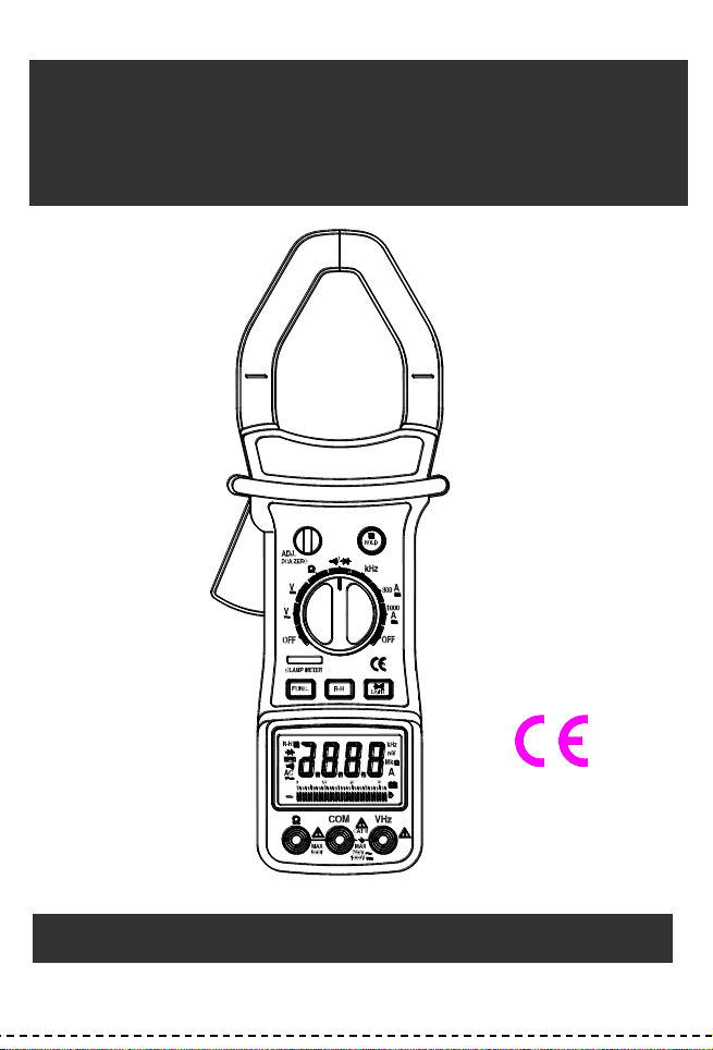
AC / DC CLAMP METER
◆⧫ ◼

CONTENTS PAGE
SAFETY INFORMATION ….…………………………………………….
SAFETY SYMBOLS .…………………………………………………..
SAFETY PRECAUTIONS ……………………………………………..
MAINTENANCE .…………………………………………………….....
GENERAL DESCRIPTION …..………………………………………..
FRONT PANEL DESCRIPTION …..………………………………….
OPERATING INSTRUCTIONS ……………………………………….
SPECIFICATIONS …...………………………………………………...
REPLACING THE BATTERY ...………………………………………..
ACCESSORIES ………………………………………………………...
1
1
1
1
3
3
6
8
10
11
SAFETY INFORMATION
The AC/DC clamp meter has been designed according to IEC1010 – 1 and
IEC1010 – 2 – 032 concerning safety requirements for electrical measuring
instruments and hand – held current clamps with an overvoltage category (CAT
II) and pollution 2.
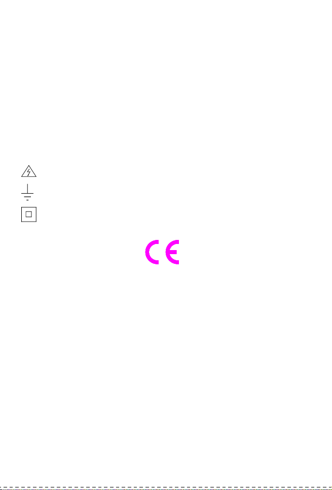
SAFETY SYMBOLS
Important safety information, refer to the operating manual.
Dangerous voltage may be present.
Earth ground.
Double insulation (Protection class II).
The AC/DC clamp meter complies with the requirements of the following
European Community Directives: 89/336/EEC (Electromagnetic Compatibility)
and 73/23/EEC (Low Voltage) as amended by 93/68/EEC (CE Marking).
However, electrical noise or intense electromagnetic fields in the vicinity of the
equipment may disturb the measurement circuit. Measuring instruments will also
respond to unwanted signals that may be present within the measurement
circuit.
Users should exercise care and take appropriate precautions to avoid
misleading.
SAFETY PRECAUTIONS
Follow all safety and operating instructions to ensure maximum personal safety
during the operation and to ensure the meter is used safely and is kept in good
operating condition.

-1-
•
•
•
•
•
•
•
Read these operating instructions thoroughly and completely before
operating your meter. Pay particular attention to WARNINGS, which will
inform you of potentially dangerous procedures. The instructions in
these warnings must be followed.
Always inspect your meter and test leads for any sign of damage or
abnormality before every use. If any abnormal conditions exist (i.e.
broken test leads, cracked cases, display not reading, etc.), do not
attempt to take any measurements.
Do not expose the instrument to direct sunlight, extreme temperature or
moisture.
Never ground yourself when taking electrical measurements. Do not
touch exposed metal pipes, outlets, fixtures, etc., which might be at
ground potential. Keep your body isolated from ground by using dry
clothing; rubber shoes, rubber mat, or any approved insulating material.
You always are careful when working with voltages above 60V dc or
30V ac rms. Keep fingers behind the probe barriers while measuring.
Never use the meter to measure voltages that might exceed the
maximum allowable input value of any function.
Never touch exposed wiring, connections or any live circuit when
attempting to take measurements.
MAINTENANCE
•
•
•
•
Before opening the case, always disconnect test leads from all
energized circuits.
Never use the meter unless the back cover is in place and fastened
completely.
Do not use abrasives or solvents on the meter. To clean it using a damp
cloth and mild detergent only.
Qualified and trained service technicians should only perform calibration
and repair of the meter.

-2-
•
Do not attempt calibration or service unless trained and another
person capable of rendering first aid and resuscitation is present.
GENERAL DESCRIPTION
The meter is an autoranging professional AC/DC clamp meter with digital and
analog display, 3200 counts and 33-segment bar graph. For measuring DC and
AC voltage, DC and AC current, Resistance, Frequency, Diode and Continuity
Test with battery operated.
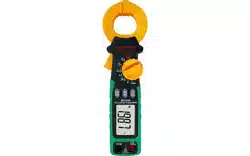
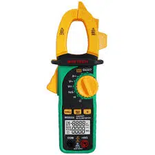
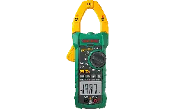
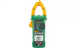
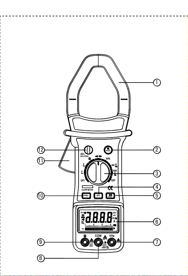
FRONT PANEL DESCRIPTION
1.
2.
3.
4.
5.
6.
Transformer jaws
Pick up the AC current or DC current flowing through the conductor.
Hold button
When this button is pushed, the display will keep the last reading and
“ ”
symbol will appear on the LCD until pushing it again.
Rotary switch
This switch is used to select functions and desired ranges as well as
to turn on/off the meter.
R-H button
In autorange, press this button to select manual range and the “R-H”
symbol will appear on the LCD.
In manual range, press this button momentarily to step up 1 range at
one time, press this button for more than 1 second to select
autorange.
The function is only for AC/DC voltage and resistance range.
LIGHT button
To use this function, press this LIGHT button. When the button is
pushed, the light of display is on. After about 3 − 5 seconds, the light
is self-off. The light is on again, just push this button once.
Display
3200 counts and 33 segments bar graph, digit is 15mm high.
-3-
7.
8.
9.
10.
11.
12.
“VHz” jack
This is positive input terminal for volt and frequency measurement
connection is made to it using the red test lead.
“COM” jack
This is negative (ground) input terminal for all measurement modes
except current. Connection is made to it using the black test lead.
“” jack
This is the positive input terminal for ohms. Connection is made to it
using the red test lead.
FUNC. button
The button is used to select
or testing in / range and to
select ACA or DCA in AC current ranges.
Trigger
Press the lever to open the transformer. When the lever is released,
the jaws will close again.
DCA ZERO
Adjusting the DCA ZERO knob, when the display is not zero reading
for does not measurement before.
-4-
AC/DC CLAMP METER LAYOUT
◆⧫ ◼

-5-
OPERATING INSTRUCTIONS
DC VOLTAGE MEASUREMENT
1.
2.
3.
4.
Connect the red test lead to the “VHz” jack and the black lead to the
“COM” jack.
Set rotary switch at desired V position.
Connect test leads across the source or load being measured.
Read voltage value on the LCD display along with the polarity of the red
lead connection.
AC VOLTAGE MEASUREMENT
1.
2.
3.
4.
Connect the red test lead to “VHz” jack and the black test lead to the
“COM” jack.
Set the rotary switch at desired V~ position.
Connect test leads across the source or load being measured.
Read voltage value on the LCD display.
AC CURRENT MEASUREMENT
1.
2.
3.
Set the rotary switch at desired 300A or 1000A position. Push Func.
button to 300A~ or 1000A~ range.
Press the trigger to open transformer jaw and to clamp one conductor
only, making sure that the jaw is firmly closed around the conductor.
Read current value on LCD display.
DC CURRENT MEASUREMENT
1.
2.
3.
4.
Set the rotary switch at desired 300A or 1000A position.
Adjusting the DCA ZERO knob until the display show “0”, when the
meter does not measurement before.
Press the trigger to open transformer jaw and to clamp one conductor
only, making sure that the jaw is firmly closed around the conductor.
Read current value on LCD display.
NOTE:

As the jaw core may remain some magnetic force after using for awhile. If the
display can not reach “0”, taking following process to correct it please:
1. Open the jaws several times.
-6-
2. Adjusting the DCA ZERO knob, making the display is “0”.
3. Then work again.
RESISTANCE MEASUREMENT
1.
2.
3.
4.
Connect the red test lead to “” jack and black test lead to the “COM”
jack (The polarity of red lead is positive “+”).
Set the rotary switch at desired ”” range position.
Connect test leads across the resistor to be measured and read LCD
display.
If the resistance being measured is connected to a circuit,turn off power
and discharge all capacitors before applying test leads.
NOTE:
1.
If the resistance being measured exceeds the maximum value of the
range selected or the input is not connected, an overrange indication
“OL”will be displayed.
2.
3.
4.
When checking in-circuit resistance, be sure the circuit under test has all
power removed and that all capacitors have been discharged fully.
For measuring resistance above 1M, the meter may take a few
seconds to get stable reading. This is normal for high resistance
measurements.
When the input is not connected, i.e. at open circuit, the figure “OL” will
be displayed for the overrange condition.
MEASURING FREQUENCY
1.
2.
3.
4.
Connect the red test lead to “VHz” jack and the black test lead to the
“COM” jack.
Set the rotary switch at desired kHz position.
Connect test leads across the source or load being measured.
Read frequency value on the LCD display.
NOTE:

The input voltage should be between 200mV and 10V rms. ac. If the voltage is
more than 10V rms. reading may be out of the accuracy range.
-7-
AUDIBLE CONTINUITY AND DIODE TEST
1.
2.
3.
4.
Connect red test lead to “” jack, black test lead to “COM” jack. The
polarity of red lead connection is positive “+”.
Set range switch to “ / ” position and push the FUNC. button to
select audible continuity or diode test mode.
If audible continuity is selected, connect test leads to two points of circuit
to be tested. If continuity exists, built-in buzzer will sound.
If diode test mode is selected, connect the red and black leads to the
anode and cathode of the diode under test. The forward voltage drop of
this diode in V will be displayed.
SPECIFICATIONS
Accuracy is specified for a period of one year after calibration and at 18℃ to
28℃ (64F to 82F) with relative humidity to 80%.
GENERAL
Maximum voltage between
terminals and earth ground
: CAT II 1000V dc or 750V ac rms. (sine)
Display
: LCD, 3200 counts and 33 segments bar graph
updates 2-3/sec.
Ranging method
: Auto / Manual
Polarity indication
: “-” displayed for negative polarity
Overrange indication
: Only figure “OL” on the display
Jaw opening capability
: 55mm (Max conductor size)
Power
: 9V battery, NEDA 1604 or 6F22 006P
Low battery indication
: “ ” appears on the display
Operating environment
: 0 to 40℃
Storage temperature
: -10℃ to 50℃
Temperature coefficient
: 0.1×specified accuracy) /℃ ( <18℃ or >28℃ )
Altitude
: 2000m
Size
: 282mm×104mm×47mm
Weight
: Approx. 550g.
-8-
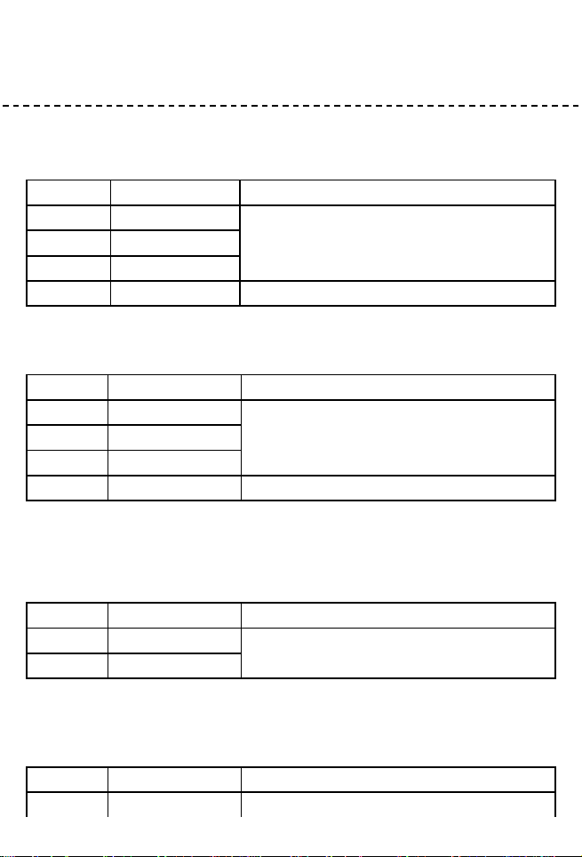
DC VOLTAGE
Range
Resolution
Accuracy
3V
1mV
0.8% of rdg 1 digit
30V
10mV
300V
0.1V
1000V
1V
1.0% of rdg 2 digits
Input Impedance: 10M
AC VOLTAGE
Range
Resolution
Accuracy
3V
1mV
1.0% of rdg 5 digits
30V
10mV
300V
0.1V
750V
1V
1.2 % of rdg 5 digits
Input Impedance: 10M
Frequency range: 40Hz to 200Hz.
Response: Average responding, calibrated in rms. of a sine wave.
AC CURRENT
Range
Resolution
Accuracy
300A
0.1A
600A 2.0% of rdg 10 digits
600A 3.0% of rdg 10 digits
1000A
1A
Overload Protection: 1000A for 60 seconds maximum.
Frequency range: 50Hz to 60Hz.
DC CURRENT
Range
Resolution
Accuracy
300A
0.1A
600A 2.0% of rdg 5 digits
1000A
1A
600A 3.0% of rdg 5 digits
Overload Protection: 1000A for 60 seconds maximum.
-9-
RESISTANCE
Range
Resolution
Accuracy
300
0.1
2.0% of rdg 10 digits
3k
1
30k
10
300k
0.1k
3M
1k
30M
10k
2.5% of rdg 10 digits
Maximum Open Circuit Voltage: 1.3V
Overload Protection: 250V dc or rms. ac for all ranges.
FREQUENCY
Range
Resolution
Accuracy
30kHz
10Hz
2.0% of rdg 10 digits
Sensitivity: 200mV rms.
Input Limit: 250V ac.
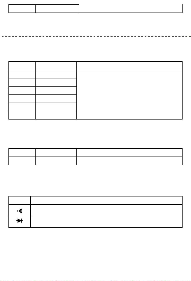
AUDIBLE CONTINUITY AND DIODE
Range
Description
If continuity exists (about less than 18), built-in buzzer will sound.
Show the approx. Forward voltage of the diode.
REPLACING THE BATTERY
WARNING
Before attempting to open the case of battery, always be sure that test leads
have been disconnected from measurement circuits. Close case and tighten

screws completely before using the meter to avoid electrical shock hazard.
If “ ” appears on display, it indicates that the battery should be replaced.
Use the following procedure to replacing the battery:
-10-
1. Disconnect test leads from any live source, turn the rotary switch to OFF,
and remove the test leads from the input terminals.
2. The battery cover is secured to the bottom case by a screw. Using a
screwdriver, remove the screw from the battery cover and remove the
battery cover.
3. Remove battery and replace with a new equivalent 9 volt battery.
4. Replace the battery cover and reinstall the screw.
ACCESSORIES
• Operator’s instruction manual
• Set of test leads
• Gift box
• 9 volt battery. NEDA 1604 6F22 006P type
CAUTION:
Using this appliance in an environment with a strong radiated radio-frequency
electromagnetic field (approximately 3V/m),may influence its measuring accuracy.
The accuracy can be reduced to (12% of reading + 6 digits).
The measuring result can be strongly deviating from the actual value.
The measuring result can be strongly deviating from the actual value.

The measuring result can be strongly deviating from the actual value.
The measuring result can be strongly deviating from the actual value.
-11-

700007869