USER’S MANUAL
%°C°F
MkΩHz
NCV
nμFVA
MAX-MINAVGREL
INR
AUTO
600/
60
NCV
Hz
mA
6000 Counts
T-Rms
REL
FUNC
RANGE
MAX
Hz%
MIN
B.L.
HOLD
COM
INPUT
DIGITAL CLAMP METER
ACCLAM PMETE R

USER’S MANUAL
%°C°F
MkΩHz
NCV
nμFVA
MAX-MINAVGREL
INR
AUTO
600/
60
NCV
Hz
mA
6000 Counts
T-Rms
REL
FUNC
RANGE
MAX
Hz%
MIN
B.L.
HOLD
COM
INPUT
DIGITAL CLAMP METER
ACCLAM PMETE R

CONTENTS CONTENTS
1. Safety Information.............................1
1.1 Preliminary...............................................1
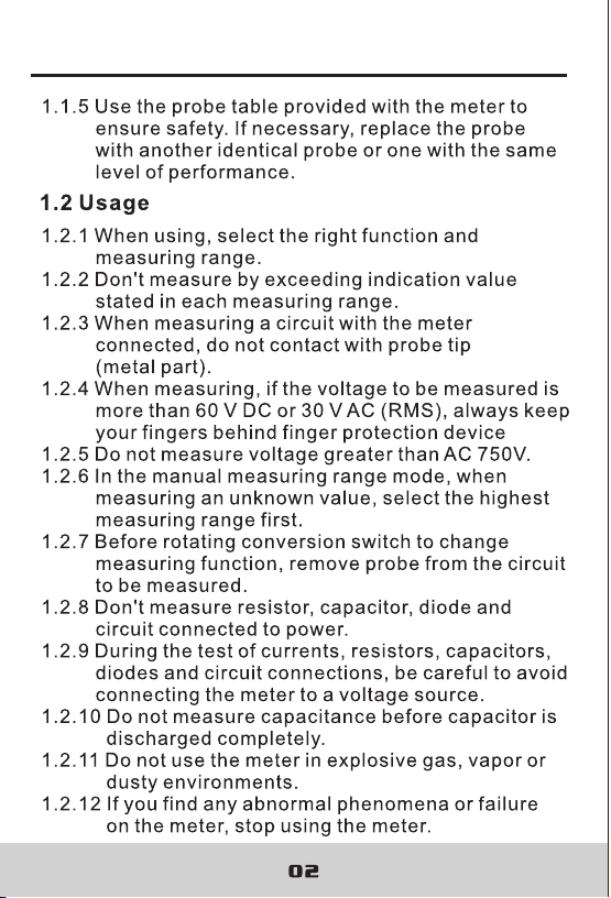
1.2 Usage.......................................................2
1.3 Mark.........................................................3
1.4 Maintenance............................................3
2. Description........................................4
2.1 Part Name................................................5
2.2 Switch and Button Description..................7
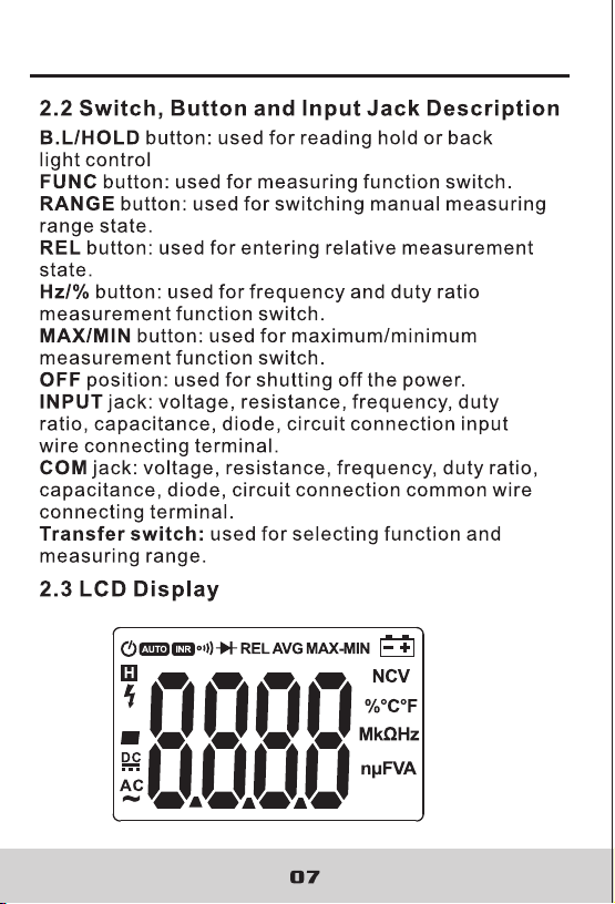
2.3 LCD Display.............................................7
3. Specifications...................................9
3.1 General ...................................................9
3.2 Technique Data.......................................10
4. Operating Guidance.........................15
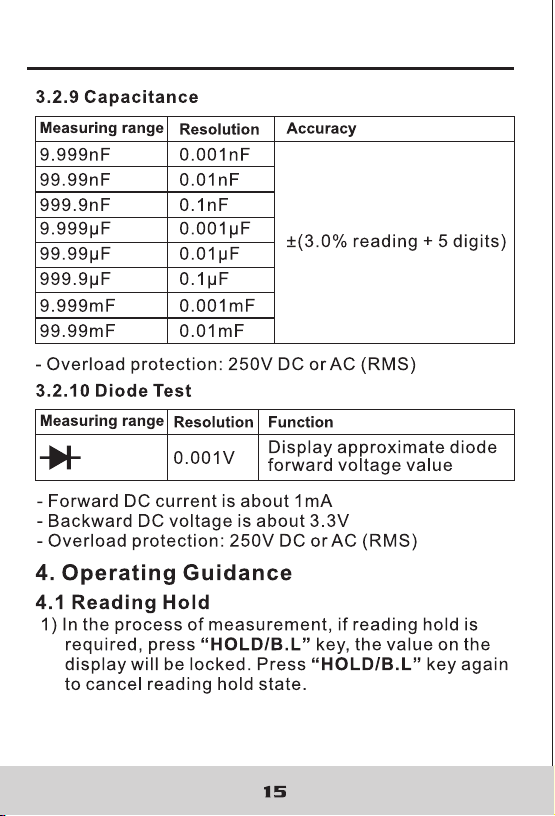
4.1 Reading Hold..........................................15
4.2 Measuring Range Switch.........................16
4.3 Frequency/Duty Ratio Switch...................16
4.4 Maximum/Minimum
Measurement Choice..........................17
4.5 Function Choice.......................................17
4.6 Relative Measurement
And Surge Measurement.......................18
4.7 Back Light And Clamp Head Light.............18
4.8 Automatic Power-Off ...............................19
4.9 Measurement Preparation........................19
4.10 Current Measurement.............................20
4.11 Voltage Measurement.............................21
4.12 Frequency And Duty
Ratio Measurement..............................22
4.13 Resistance Measurement.......................24
4.14 Diode Test..............................................25
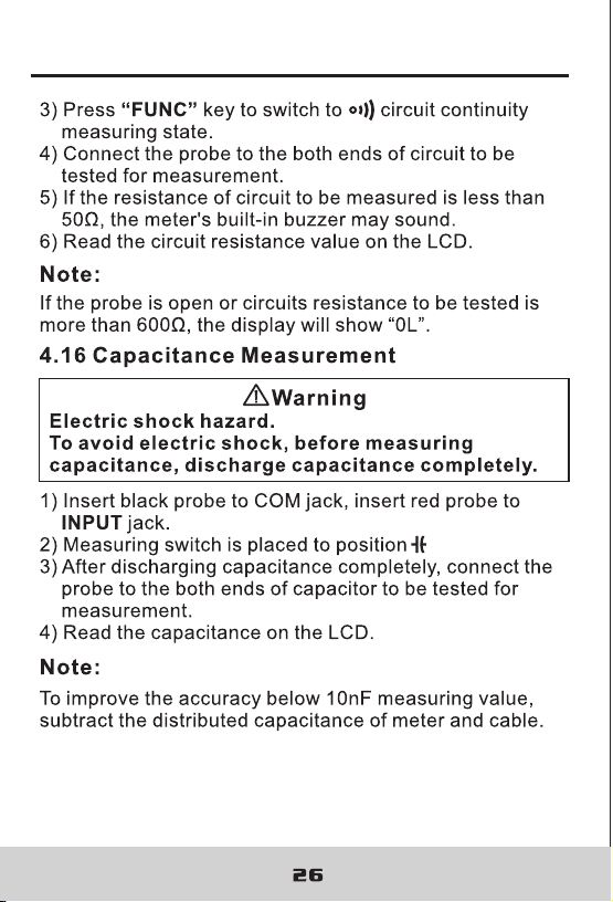
4.15 Circuit Continuity Test.............................25
4.16 Capacitance Measurement.....................26
5. Maintenance......................................27
5.1 Replace Battery.........................................27
5.2 Replace Probe..........................................28
6. Attachments.......................................28
4.17 NCV Measurement.................................27
DIGITAL CLAMP METER DIGITAL CLAMP METER

CONTENTS CONTENTS
1. Safety Information.............................1
1.1 Preliminary...............................................1
1.2 Usage.......................................................2
1.3 Mark.........................................................3
1.4 Maintenance............................................3
2. Description........................................4
2.1 Part Name................................................5
2.2 Switch and Button Description..................7
2.3 LCD Display.............................................7
3. Specifications...................................9
3.1 General ...................................................9
3.2 Technique Data.......................................10
4. Operating Guidance.........................15
4.1 Reading Hold..........................................15
4.2 Measuring Range Switch.........................16
4.3 Frequency/Duty Ratio Switch...................16
4.4 Maximum/Minimum
Measurement Choice..........................17
4.5 Function Choice.......................................17
4.6 Relative Measurement
And Surge Measurement.......................18
4.7 Back Light And Clamp Head Light.............18
4.8 Automatic Power-Off ...............................19
4.9 Measurement Preparation........................19
4.10 Current Measurement.............................20
4.11 Voltage Measurement.............................21
4.12 Frequency And Duty
Ratio Measurement..............................22
4.13 Resistance Measurement.......................24
4.14 Diode Test..............................................25
4.15 Circuit Continuity Test.............................25
4.16 Capacitance Measurement.....................26
5. Maintenance......................................27
5.1 Replace Battery.........................................27
5.2 Replace Probe..........................................28
6. Attachments.......................................28
4.17 NCV Measurement.................................27
DIGITAL CLAMP METER DIGITAL CLAMP METER
DIGITAL CLAMP METER DIGITAL CLAMP METER
DIGITAL CLAMP METER DIGITAL CLAMP METER
03 04
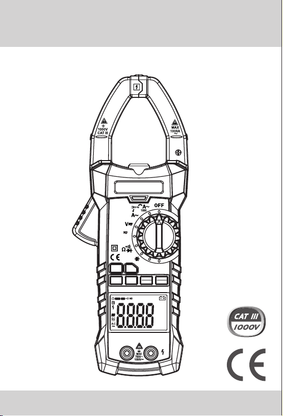
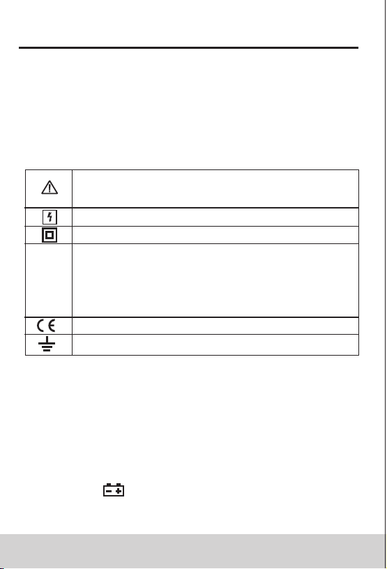
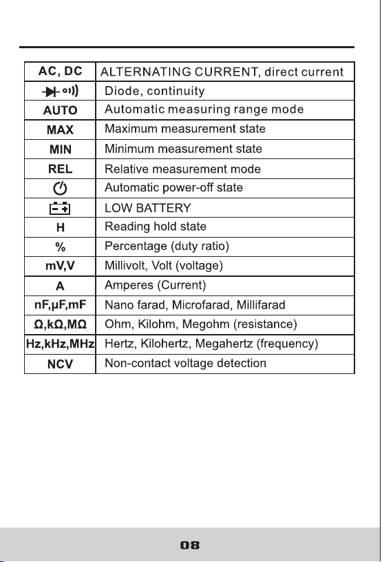
1.3 Mark
Note (Important safety information. Refer to
the operation manual)
Can be used for dangerous electric conductor.
Double insulation protection (class II)
CAT III According to pulse voltage tolerance
protection level provided by IEC 61010-1
standard overvoltage (installation) level III and
pollution degree 2.
The meter complies with EU standard
Grounding
1.4 Maintenance
1.4.1 Don't try to open the meter bottom case to adjust
or repair. Such operations can only be performed
by technicians who fully understand the meter and
electrical shock hazard.
1.4.2 Before opening the meter bottom case or battery
cover, remove probe from the circuit to be measured.
1.4.3 To avoid wrong readings causing electric shock,
when " " appears on the meter display, replace
the battery immediately.
2. Description
- The meter is a portable, professional measuring
instrument with LCD display and back light for easy
reading by users. Measuring range switch is operated
by single hand for easy operation with overload
protection and low battery indicator. It is an ideal
multifunction meter for professionals, factories,
schools, fans and family use.
- The meter is used for AC current, DC current, voltage,
DC voltage, frequency, duty ratio, resistance,
capacitance measurement, circuit connection, diode
test and non-contact voltage detection.
- The meter has automatic measuring range and manual
measuring range.
- The meter has reading hold function.
- The meter has max. measuring function.
- The meter has min. measuring function.
- The meter has clamp head frequency measurement
function.
- The meter has auto power-off function.
- The meter has relative measuring function.
1.2.13 Unless the meter bottom case and the battery
cover are completely fastened completely, do
not use the meter.
1.2.14 Don't store or use the meter in the conditions
of direct sunlight, high temperature and high
humidity.
1.4.4 Clean the meter with damp cloth and mild detergent.
Do not use abrasives or solvents.
1.4.5 Power off the meter when the meter is not used.
Switch the measuring range to OFF position.
1.4.6 If the meter is not used for long time, remove the
battery to prevent the meter being damaged.
DIGITAL CLAMP METER DIGITAL CLAMP METER

03 04
1.3 Mark
Note (Important safety information. Refer to
the operation manual)
Can be used for dangerous electric conductor.
Double insulation protection (class II)
CAT III According to pulse voltage tolerance
protection level provided by IEC 61010-1
standard overvoltage (installation) level III and
pollution degree 2.
The meter complies with EU standard
Grounding
1.4 Maintenance
1.4.1 Don't try to open the meter bottom case to adjust
or repair. Such operations can only be performed
by technicians who fully understand the meter and
electrical shock hazard.
1.4.2 Before opening the meter bottom case or battery
cover, remove probe from the circuit to be measured.
1.4.3 To avoid wrong readings causing electric shock,
when " " appears on the meter display, replace
the battery immediately.
2. Description
- The meter is a portable, professional measuring
instrument with LCD display and back light for easy
reading by users. Measuring range switch is operated
by single hand for easy operation with overload
protection and low battery indicator. It is an ideal
multifunction meter for professionals, factories,
schools, fans and family use.
- The meter is used for AC current, DC current, voltage,
DC voltage, frequency, duty ratio, resistance,
capacitance measurement, circuit connection, diode
test and non-contact voltage detection.
- The meter has automatic measuring range and manual
measuring range.
- The meter has reading hold function.
- The meter has max. measuring function.
- The meter has min. measuring function.
- The meter has clamp head frequency measurement
function.
- The meter has auto power-off function.
- The meter has relative measuring function.
1.2.13 Unless the meter bottom case and the battery
cover are completely fastened completely, do
not use the meter.
1.2.14 Don't store or use the meter in the conditions
of direct sunlight, high temperature and high
humidity.
1.4.4 Clean the meter with damp cloth and mild detergent.
Do not use abrasives or solvents.
1.4.5 Power off the meter when the meter is not used.
Switch the measuring range to OFF position.
1.4.6 If the meter is not used for long time, remove the
battery to prevent the meter being damaged.
DIGITAL CLAMP METER DIGITAL CLAMP METER

%°C°F
MkΩHz
NCV
nμFVA
MAX-MINAVGREL
INR
AUTO
600/
60
NCV
Hz
mA
6000 Counts
T-Rms
REL
FUNC
RANGE
MAX
Hz%
MIN
B.L.
HOLD
COM
INPUT
05 06
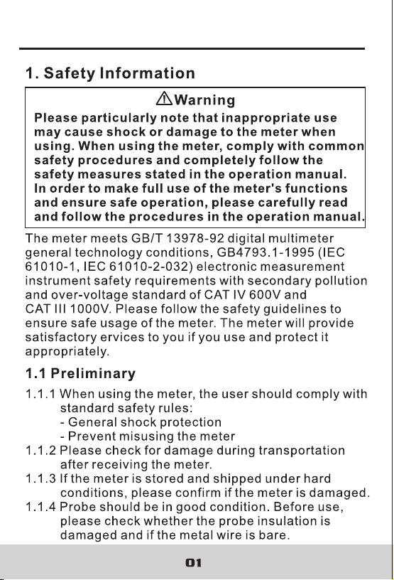
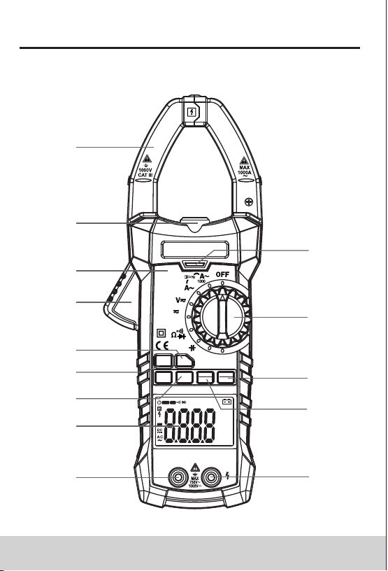
(1) Current clamp head: used for current measurement.
(2) Clamp head light
(3) Panel
(4) Trigger
(5) Function choice button (FUNC)
(6) Relative measurement button
(7) Frequency/duty ratio switch button (Hz/%)
(8) LCD display
(9) Common end jack
(10) Resistance, capacitance, voltage, frequency,
diode and continuity input jack
(11) Maximum/minimum choice button (MAX/MIN)
(12) Reading hold/Back light button (B.L/ HOLD)
(13) Transfer switch
(14) NCV indicator
2.1 Part Name
14
13
12
11
109
8
7
5
4
2
6
3
1
DIGITAL CLAMP METER DIGITAL CLAMP METER
ACCLAM PMETE R
%°C°F
MkΩHz
NCV
nμFVA
MAX-MINAVGREL
INR
AUTO
600/
60
NCV
Hz
mA
6000 Counts
T-Rms
REL
FUNC
RANGE
MAX
Hz%
MIN
B.L.
HOLD
COM
INPUT
05 06
(1) Current clamp head: used for current measurement.
(2) Clamp head light
(3) Panel
(4) Trigger
(5) Function choice button (FUNC)
(6) Relative measurement button
(7) Frequency/duty ratio switch button (Hz/%)
(8) LCD display
(9) Common end jack
(10) Resistance, capacitance, voltage, frequency,
diode and continuity input jack
(11) Maximum/minimum choice button (MAX/MIN)
(12) Reading hold/Back light button (B.L/ HOLD)
(13) Transfer switch
(14) NCV indicator
2.1 Part Name
14
13
12
11
109
8
7
5
4
2
6
3
1
DIGITAL CLAMP METER DIGITAL CLAMP METER
ACCLAM PMETE R
DIGITAL CLAMP METER DIGITAL CLAMP METER
DIGITAL CLAMP METER DIGITAL CLAMP METER
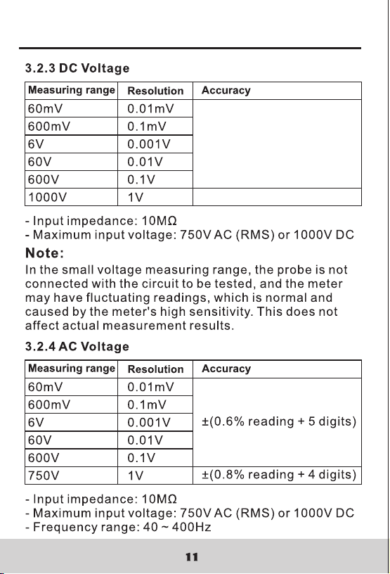
09 10
3. Specifications
Automatic measuring range and manual measuring
range.
Full measuring range overload protection.
The maximum allowable voltage between
measurement end and ground: 1000V DC or 750V AC
Operational height: maximum 2000m
Display: LCD
Displayed maximum value: 5999 digit.
Polarity indication: automatical indication, '-' means
negative polarity.
Exceeding measuring range display: '0L' or '-0L'.
Sampling rate: about 3 times/sec.
Unit display: has function and power unit display.
Auto off time: 15 min
Power supply: DC power 9V
Battery type: NEDA 1604, 6F22
Battery undervoltage indication: LCD displays
symbol.
Temperature coefficient: less than 0.1×accuracy/°C
Operational temperature: 18°C~28°C
Storage temperature: -10°C~50°C
Dimension: 238×92×50mm
Weight: about 340g (include battery)
The meter should be recalibrated under the condition
of 18°C~28°C, relative humidity less than 75% with
the period of one year.
3.1 General
3.2 Technical Indicators
Environment temperature: 23±5°C, relative humidity
(RH):<75%
3.2.1 True RMS Zero Input Characteristic
3.2.1.1 For measuring non-sinusoidal wave signal,
uses true RMS measuring method, which has
less error than traditional average response
measuring method.
3.2.1.2 The true RMS meter can accurately measure
non-sinusoidal wave signal, but if it is in AC
function mode, when there is no signal to be
measured (input terminal short circuit in AC
voltage mode), clamp meter may show a
reading from 1 to 50. These deviating readings
are normal. In the designated measurement
range, they will not affect the accuracy for
multimeter measuring AC.
3.2.1.3 The true RMS can be measured only when input
signal reaches a certain level. Therefore, the
measuring range of AC voltage and current
should be specified at 2% ~ 100% of full range.
3.2.2 AC Current
Accuracy
Resolution
Measuring range
±(2.0% reading + 8 digits)
60A
600A
1000A
0.01A
0.1A
1A
- Maximum input current: 1000A AC
- Maximum input current: 0~600A: 40~400Hz;
600A~1000A: 40~60Hz
DIGITAL CLAMP METER DIGITAL CLAMP METER
DIGITAL CLAMP METER DIGITAL CLAMP METER
±(0.5% reading + 5 digits)
±(0.8% reading + 4 digits)
DIGITAL CLAMP METER DIGITAL CLAMP METER
±(0.5% reading + 5 digits)
±(0.8% reading + 4 digits)
DIGITAL CLAMP METER DIGITAL CLAMP METER
±(1.2% reading + 3 digits)
DIGITAL CLAMP METER DIGITAL CLAMP METER
±(1.2% reading + 3 digits)
16
4.2 Manual Measuring Range
RANGE key is automatic/manual measuring range key
to trigger mode.
The preset one is automatic measuring range. Press to
switch to manual measuring range.
In the manual measuring range mode, click once to
change to upper range. Continue to the top range, then
continue to press this key to change to the bottom
range, followed by recycling. If this key is pressed more
than 2 sec, it will switch back to automatic measuring
range state.
In capacitance and frequency measurement state, rhw
manual measuring range button is invalid.
4.3 Frequency/Duty Ratio Switch
1) When the meter is in AC voltage mode, if “Hz/%”
button is pressed, the meter will measure Hz, and
measure AC voltage, AC current signal frequency.
Click “Hz/%” button again, the meter will measure
DUTY cycle, and measure voltage and current signal
duty ratio. If it is in HZ/DUTY position, pressing HZ %
key will switch between HZ and DUTY by recycling.
2) If “Hz/%” button is pressed again, the meter will
revert to voltage, current measurement state.
The meter is in the maximum/minimum value
measurement state, it can't switch to frequency, duty
ratio measurement mode.
DIGITAL CLAMP METER DIGITAL CLAMP METER

17 18
4.4 Maximum/Minimum Measurement Choice
1) Press “MAX/MIN” key to enter MAX mode, and
always keep measurement maximum value; press
“MAX/MIN” key again, the meter will enter minimum
value measurement state; press “MAX/MIN” key for
the third time, the meter will display the difference of
maximum and minimum value; press “MAX/MIN” key
to repeat the above operations by recycling.
2) After entering MAX or MIN mode, it will automatically
save the measured maximum or minimum value.
3) After entering MAX or MIN mode, it will automatically
save the measured maximum or minimum value.
4) If the user presses “MAX/MIN” key more than 2 sec,
the meter will restore normal measuring range.
Note:
1) When the meter is in the maximum/minimum value
measurement state, it is in manual measuring range
mode.
2) When the meter is in the frequency, duty ratio
measurement state, it can't switch to
maximum/minimum value measurement mode.
1) In the resistance mode, press "FUNC" button, it will
switch among resistance, diode and continuity
detection by recycling.
2) In the voltage and current mode, press "FUNC"
button to switch between AC and DC.
4.5 Function Switch
1) REL/INRUSH button is relative value measurement
button. Operated by tapping this button, it will enter
relative value measurement mode,. The current
display value can be stored in the memory as
reference value. When the user measures later, the
display value is the difference for input value minus
reference value. ie. REL (current reading)= Input
value - Reference value.
2) The relative value measurement can only be
performed in the manual mode.
1) In the process of measurement, if ambient light is too
dark to read, press “B.L/HOLD” key to open the
backlight, the backlight will automatically turn off after
about 30 seconds.
2) During this period, pressing “B.L/ HOLD” key more
than two seconds will turn off backlight.
3) In the current mode, the meter will turn on backlight
and, at the same time, it will turn on clamp head light.
Backlight is LED with high current draw. The backlight
will turn off in about 30 seconds. If backlight is used
often, it will shorten battery life, so do not use
backlight excessively.
4.6 REL/INRUSH Measurement
4.7 Back Light And Clamp Head Light
DIGITAL CLAMP METER DIGITAL CLAMP METER
19 20
Note:
When battery voltage < 7.2V, the LCD displays “ ”
(undervoltage) symbol. When the user uses the
backlight, the battery voltage drops below 7.2 V, due to
high working current. The “ ”symbol may appear, and
measurement accuracy is not guaranteed. Contimue
to use the meter normally without using backlight.
Do not replace the battery until “ ” symbol shows
under normal cnditions.
4.8 Automatic Power-Off
1) If there is no operation during any 15 minutes after
turning the machine on, the meter will enter
suspended state, automatically powering off to save
the battery. Within 1 minute before shutdown, buzzer
will sound five times. The meter will then enter a
dormant state.
2) After automatic power-off, press FUNC key, the
meter will turn on again.
3) If the user holds “FUNC” key when powering on, it
will cancel automatic power-off function.
4.9 Measurement Preparation
1) Turn the transfer switch to turn on the power. When
battery voltage is low (about<7.2V), LCD displays
“ ” symbol, Replace the battery.
2) “ ” symbol means that input voltage or current
should not be more than the specified value, which
is to protect the internal line from damage.
3) Place transfer switch to required measuring function
and range.
4) When connecting line, first connect the common
test line, then connect charged test line. When
removing line, remove charged test line first.
4.10 Current Measurement
Electric shock hazard.
Remove the probe from the meter before
measuring with current clamp.
Warning
1) Measuring switch is placed to position A. At this time,
the meter is in AC current measurement state.
Choose appropriate measuring range.
2) Hold the trigger, open clamp head, clip one lead of
measurement circuit to be tested in the clamp.
3) Read the current value on the LCD display.
Note:
1) Clamping two or more leads of circuit to be tested
simultaneously will not get the correct measuring
results.
2) To get accurate reading, connect the lead to be
tested at the center of current clamp.
3) “ ”indicates that maximum input AC current is 1000 A.
DIGITAL CLAMP METER DIGITAL CLAMP METER
21 2 2
4.11 Voltage Measurement
Electric shock hazard.
Pay special attention to avoid shock when
measuring high voltage.
Don't input voltage more than AC750 RMS.
Warning
1) Insert black probe to COM jack, insert red probe to
INPUT jack, choose appropriate measuring range.
2) Place transfer switch to AC voltage or position.
At this time, the meter is in the DC voltage
measurement state. To measure AC voltage, press
FUNC button to enter AC voltage measurement state.
3) Connect the probe with voltage source or both ends
of load in parallel for measurement.
4) Read the voltage on the LCD.
Note:
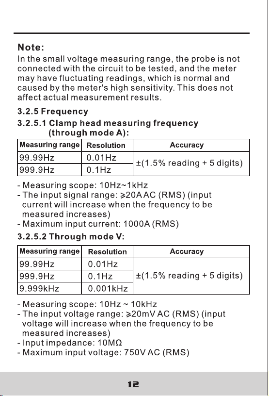
1) In the small voltage measuring range, the probe is
not connected with the circuit to be tested, and the
meter may have fluctuating readings, which is normal
and caused by the meter's high sensitivity. When the
meter is connected with the circuit to be tested, you
will get actual measured value.
2) In the relative measurement mode, automatic
measuring range is invalid.
3) “ ”indicates that maximum input voltage is 750V AC
or 1000V DC. Maximum input voltage at mode mV is
600mV DC or AC.
4) If the readings measured by the meter is more than
750V rms AC, it will send out "beep" alarm.
V
mV
4.12 Frequency And Duty Ratio Measurement
Electric shock hazard.
Remove the probe from the meter before
measuring with current clamp.
Warning
(1) Measuring switch is placed to position A.
(2) Hold the trigger, open clamp head, clip one lead of
measurement circuit to be tested in the clamp.
(3) Press Hz/% key to switch to frequency measuring
state.
(4) Rad the current value on the LCD display.
(5) Pressing Hz/% again can enter duty ratio measuring
state.
1) Clamp head measuring frequency
(through AC current):
Note:
(1) Clamping two or more leads of circuit to be tested
simultaneously will not get the correct measuring
results.
(2) Frequency measurement range is 10Hz~1kHz. If the
frequency to be tested is less than 10Hz, or if
frequency is higher than 10 kHz, accuracy is not
guaranteed.
(3) Duty ratio measuring range is 10 ~ 95%.
(4) “ ”means that maximum input current is
1000A AC (RMS).
DIGITAL CLAMP METER DIGITAL CLAMP METER
21 2 2
4.11 Voltage Measurement
Electric shock hazard.
Pay special attention to avoid shock when
measuring high voltage.
Don't input voltage more than AC750 RMS.
Warning
1) Insert black probe to COM jack, insert red probe to
INPUT jack, choose appropriate measuring range.
2) Place transfer switch to AC voltage or position.
At this time, the meter is in the DC voltage
measurement state. To measure AC voltage, press
FUNC button to enter AC voltage measurement state.
3) Connect the probe with voltage source or both ends
of load in parallel for measurement.
4) Read the voltage on the LCD.
Note:
1) In the small voltage measuring range, the probe is
not connected with the circuit to be tested, and the
meter may have fluctuating readings, which is normal
and caused by the meter's high sensitivity. When the
meter is connected with the circuit to be tested, you
will get actual measured value.
2) In the relative measurement mode, automatic
measuring range is invalid.
3) “ ”indicates that maximum input voltage is 750V AC
or 1000V DC. Maximum input voltage at mode mV is
600mV DC or AC.
4) If the readings measured by the meter is more than
750V rms AC, it will send out "beep" alarm.
V
mV
4.12 Frequency And Duty Ratio Measurement
Electric shock hazard.
Remove the probe from the meter before
measuring with current clamp.
Warning
(1) Measuring switch is placed to position A.
(2) Hold the trigger, open clamp head, clip one lead of
measurement circuit to be tested in the clamp.
(3) Press Hz/% key to switch to frequency measuring
state.
(4) Rad the current value on the LCD display.
(5) Pressing Hz/% again can enter duty ratio measuring
state.
1) Clamp head measuring frequency
(through AC current):
Note:
(1) Clamping two or more leads of circuit to be tested
simultaneously will not get the correct measuring
results.
(2) Frequency measurement range is 10Hz~1kHz. If the
frequency to be tested is less than 10Hz, or if
frequency is higher than 10 kHz, accuracy is not
guaranteed.
(3) Duty ratio measuring range is 10 ~ 95%.
(4) “ ”means that maximum input current is
1000A AC (RMS).
DIGITAL CLAMP METER DIGITAL CLAMP METER
DIGITAL CLAMP METER DIGITAL CLAMP METER
DIGITAL CLAMP METER DIGITAL CLAMP METER
DIGITAL CLAMP METER DIGITAL CLAMP METER
DIGITAL CLAMP METER DIGITAL CLAMP METER
27
4.17 NCV Measurement
1) Turn the meter to NCV mode.
2) Place the meter top close to the conductor. When
test voltage is greater than 110 Vac (RMS), when the
meter is close to the conductor, the meter induction
voltage indicator will turn on and the buzzer will give
an alternating high-low alarm sound.
1: Even there is no indication, voltage may exist still.
Don't use non-contact voltage detector to judge
whether there is voltage in the wire. Detection
operation could be affected by socket design,
insulation thickness, type and other factors.
2: When inputting voltage on the meter input terminal,
due to the existence of the induced voltage, voltage
induction indicator also may light.
3: External sources of interference (such as flashlight,
motor, etc.) may incorrectly trigger non-contact
voltage detection.
Note:
5. Maintenance
5.1 Replace Battery
Before opening the meter battery cover, remove
probe from the circuit to be measured to avoid
electric shock.
Warning
1) When the battery symbol “ ” appears, the battery
should be replaced immediately.
2) Unscrew the fastening screw of the battery cover
and remove the cover.
3) Replace battery.
4) Put the battery cover back as before.
The battery polarity can't be reversed.
Note:
5.2 Replace Probe
When replacing probe, replaceit with another
identical probe or one with the same level of
performance. The probe should be in good
condition. Probe level: 1000V, 10A.
Warning
If the probe is damaged, such as naked metal wire,
replace the probe.
6. Accessories
Level: 1000V 10A
One pair
1)
2)
3)
1 PCS
Probe
6F22 9VOLTS
Battery
Operation Manual
R-00-05-0785
DIGITAL CLAMP METER DIGITAL CLAMP METER