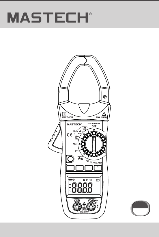
MS2026
MS2026R
Use’s Manual
DIGITAL CLAMP METER
AUTO
μnF
%Hz
kMΩ
mVA
REL
MAX MIN
DC
AC
MS2026
FUNC.
RANGE
MAX/MIN
HOLD
Hz/%
Auto Range
AC CLAMP METER
CAT III
600 V

CONTENTS
1. Safety Information….......................1
1.1 Preliminary........................................1
CONTENTS
1.2 During Use.........................................2
1.3 Symbols............................................3
1.4 Maintenance......................................3
2. Description….................................4
2.1 Names of Parts..................................5
2.2 Switch, Buttons and Input Jacks...........7
2.3 LCD (Liquid-crystal display)................8
3. Specifications….............................9
3.1 General Specifications........................9
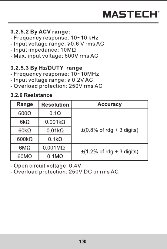
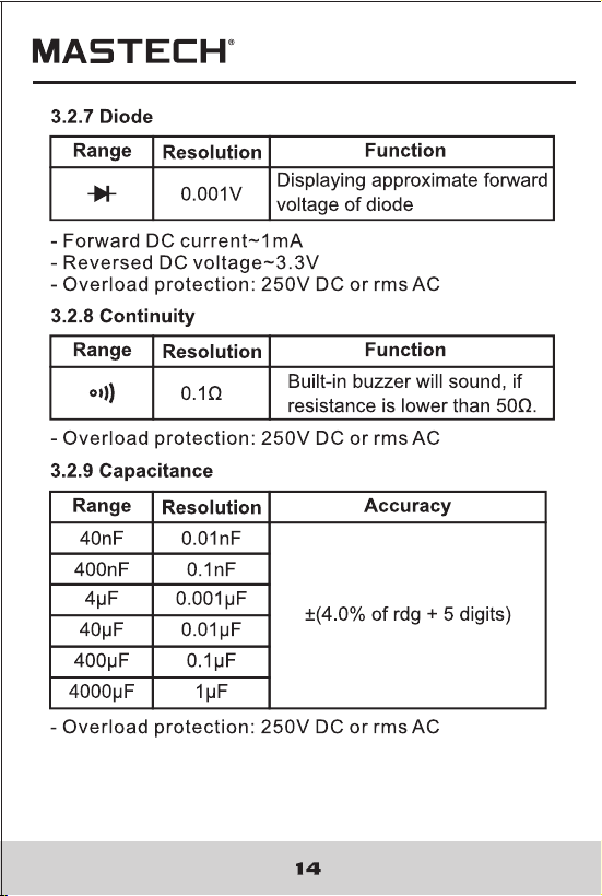
3.2 Technical Specifications.....................10
4. Operation Instruction....................15
4.1 Holding Readings..............................15
4.2 Switching REL...................................15
4.3 Switching Frequency or Duty..............15
4.4 Switching Maximum
or Minimum Value.........................16
4.5 Switching Functions..............................16
4.6 Back Light and
Clamp Lighting Bulb..........................17
4.7 Auto Power Off....................................18
4.8 Preparing for Measurement.................18
4.9 Measuring AC Current.........................18
4.10 Measuring AC Voltage.......................19
4.11 Measuring DC Voltage.......................20
4.12 Measuring Frequency........................21
4.13 Measuring Duty................................23
4.14 Measuring Resistance......................26
4.15 Testing Diode...................................27
4.16 Testing Continuity.............................28
4.17 Measuring Capacitance....................29
5. Maintenance...................................30
5.1 Replacing The Batteries......................30
5.2 Replacing Test Leads..........................30
6. Accessories....................................31

CONTENTS
1. Safety Information….......................1
1.1 Preliminary........................................1
CONTENTS
1.2 During Use.........................................2
1.3 Symbols............................................3
1.4 Maintenance......................................3
2. Description….................................4
2.1 Names of Parts..................................5
2.2 Switch, Buttons and Input Jacks...........7
2.3 LCD (Liquid-crystal display)................8
3. Specifications….............................9
3.1 General Specifications........................9
3.2 Technical Specifications.....................10
4. Operation Instruction....................15
4.1 Holding Readings..............................15
4.2 Switching REL...................................15
4.3 Switching Frequency or Duty..............15
4.4 Switching Maximum
or Minimum Value.........................16
4.5 Switching Functions..............................16
4.6 Back Light and
Clamp Lighting Bulb..........................17
4.7 Auto Power Off....................................18
4.8 Preparing for Measurement.................18
4.9 Measuring AC Current.........................18
4.10 Measuring AC Voltage.......................19
4.11 Measuring DC Voltage.......................20
4.12 Measuring Frequency........................21
4.13 Measuring Duty................................23
4.14 Measuring Resistance......................26
4.15 Testing Diode...................................27
4.16 Testing Continuity.............................28
4.17 Measuring Capacitance....................29
5. Maintenance...................................30
5.1 Replacing The Batteries......................30
5.2 Replacing Test Leads..........................30
6. Accessories....................................31
01
02
1. Safety Information
1.2 During Use
This meter has been designed according to IEC-61010
concerning electronic measuring instruments with an
overvoltage category CAT III 600V and pollution 2.
Follow all safety and operating instructions to ensure
safe useof the meter.
With proper use and care, this digital multimeter will
give you years of satisfactory service.
1.1 Preliminary
1.1.1 When using the meter, the user must observe all
normal safety rules concerning:
- General protection against electric shock
- Protection of the meter against misuse
1.1.2 When the meter is delivered, check whether it has
been damaged in transit.
1.1.3 After being stored and delivered under harsh
conditions, the meter should be checked and
confirmed whether any damages have
been incurred.
1.1.4 Test leads must be kept in good condition. Before
using check whether the insulation on test leads
has been damaged and any wire has been exposed.
1.2.1 Use the right input jack, function and range.
1.2.2 Do not take measurements that exceed the
protection limit values indicated in the
specifications.
1.2.3 Do not touch the metal tips of the test leads when
the meter is connected to the circuit to be measured.
1.2.4 Keep your fingers behind the probe barriers when
taking a measurement with an effective voltage
above 60V DC or 30V rms AC.
1.2.5 Do not take voltage measurement if the value
between the terminals and earth ground
exceeds 600V.
1.2.6 Select the highest range if the value scale to be
measured in the manual range is unknown.
1.2.7 Disconnect the test leads from the circuit under
test before turning the rotary selector to change
functions.
1.2.8 Do not measure the resistance, capacitance,
diode or continuity of live circuits.
1.2.9 Do not connect the meter to any voltage source
while the rotary selector is in the current,
resistance, capacitance, diode or continuity range.
1.2.10 Do not take capacitance measurements until the
capacitor to be measured has been fully
discharged.
1.2.11 Do not use the meter near explosive gases, steam
or dirt.
WARNING
BE EXTREMELY CAREFUL WHEN USING THIS
METER. Improper use of this device can result
in electric shock or destruction of the meter.
Take all normal safety precautions and follow
the safeguards suggested in this manual.
To exploit full functionality of the meter and
ensure safe operation, please read carefully and
follow the directions in this manual.
1.1.5 Use the test leads supplied to ensure operation
safety. If required, they must be replaced with test
leads of the same model or class.
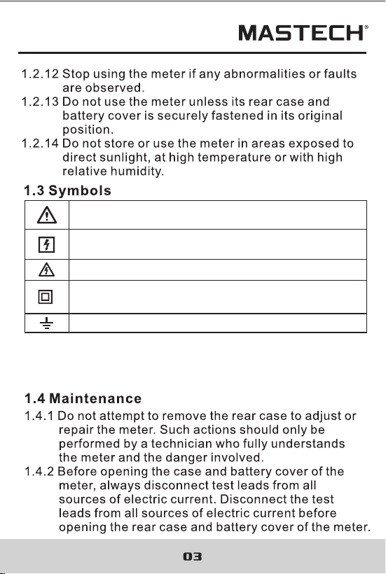
Note-Important safety information, refer to the
instruction manual.
Earth (ground) TERMINAL
Caution, possibility of electric shock
Equipment protected throughout by double
insulation or reinforced insulation.
Application around and removal from UNINSULATED
HAZARDOUS LIVE conductors is permitted.
CAT III: MEASUREMENT CATEGORY III is applicable to
test and measuring circuits connected to the distribution
part of the building's low-voltage MAINS installation.

05
06
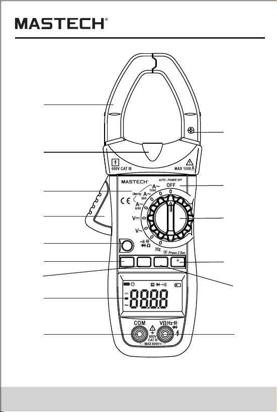
(1) Current Clamp
(2) Clamp Lighting Bulb
(3) Panel
(4) Trigger
(5) Function Switch Button (FUNC)
(6) MAX/MIN Switch Button (MAX/MIN)
(7) manual Button (RANGE)
(8) Liquid Crystal Display (LCD)
(9) COM Jack
(10) Input Jack
(11) Hz/Duty Switch Button (Hz/%)
(12) Reading Hold/Back Light Button (HOLD/B.L)
(13) Rotary selector
(14) OFF - power switch
(15) “+” Symbol
(16) “-” Symbol
(17) Rear Case
(18) Fixing Screw of Battery Cover
(19) Battery Cover
2.1 Names of Components
1
2
3
4
5
7
6
8
9 10
11
12
13
14
15
AUTO
μnF
%Hz
kMΩ
mVA
REL
MAX MIN
DC
AC
MS2026
FUNC.
RANGE
MAX/MIN
HOLD
Hz/%
Auto Range
AC CLAMP METER
05
06
(1) Current Clamp
(2) Clamp Lighting Bulb
(3) Panel
(4) Trigger
(5) Function Switch Button (FUNC)
(6) MAX/MIN Switch Button (MAX/MIN)
(7) manual Button (RANGE)
(8) Liquid Crystal Display (LCD)
(9) COM Jack
(10) Input Jack
(11) Hz/Duty Switch Button (Hz/%)
(12) Reading Hold/Back Light Button (HOLD/B.L)
(13) Rotary selector
(14) OFF - power switch
(15) “+” Symbol
(16) “-” Symbol
(17) Rear Case
(18) Fixing Screw of Battery Cover
(19) Battery Cover
2.1 Names of Components
1
2
3
4
5
7
6
8
9 10
11
12
13
14
15
AUTO
μnF
%Hz
kMΩ
mVA
REL
MAX MIN
DC
AC
MS2026
FUNC.
RANGE
MAX/MIN
HOLD
Hz/%
Auto Range
AC CLAMP METER

07
08
2.2 Switch, Buttons and Input Jacks
HOLD/B.L Button
- For holding the reading or control back light
FUNC Button
- For switching among measuring functions
RAN Button
- The key is the Auto/Manual measurement key.
Hz/% Button
- For switching between frequency and duty measuring
functions.
MAX/MIN Button
- For switching between maximum and minimum value
measuring function.
Rotary Selector
- For selecting functions and ranges.
OFF Position
- for turning off the power.
INPUT Jack
- For measuring voltage, resistance, frequency, duty,
capacitance, diode, and continuity.
COM Jack
- Common input connection for current, voltage,
resistance, frequency, duty, capacitance, diode,
continuity measurement.
Clamp
- For measuring current
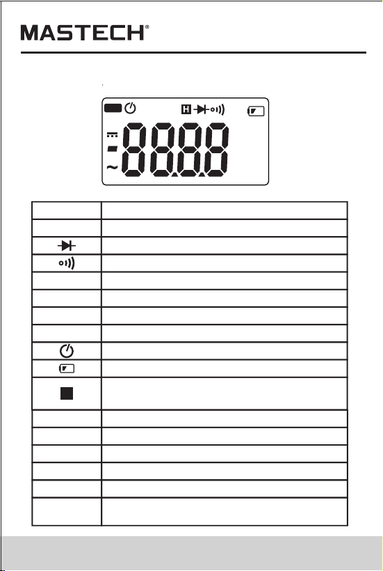
2.3 LCD (Liquid-crystal display)
AC
DC
ALTERNATING CURRENT
Direct current
Diode test
Continuity buzzer
AUTO
Auto range mode
The maximum value is being measured
MAX
MIN
The minimum value is being measured
REL
DCA zero and relative measure
Auto power off
Battery low
This indicates that the display data is
being held.
%
Percent (Duty cycle)
H
Milli-volts, Volts (Voltage)
mV, V
A
Amperes (Current)
nF, μF
Nanofarad, Microfarad
Ohms,Kilo-ohms, Mega-ohms (Resistance)
Ω,kΩ, MΩ
Hz,
kHz,MHz
Hertz, Kilo-hertz (Frequency),Milohertz
AUTO
μnF
%Hz
kMΩ
mVA
REL
MAX MIN
DC
AC
07
08
2.2 Switch, Buttons and Input Jacks
HOLD/B.L Button
- For holding the reading or control back light
FUNC Button
- For switching among measuring functions
RAN Button
- The key is the Auto/Manual measurement key.
Hz/% Button
- For switching between frequency and duty measuring
functions.
MAX/MIN Button
- For switching between maximum and minimum value
measuring function.
Rotary Selector
- For selecting functions and ranges.
OFF Position
- for turning off the power.
INPUT Jack
- For measuring voltage, resistance, frequency, duty,
capacitance, diode, and continuity.
COM Jack
- Common input connection for current, voltage,
resistance, frequency, duty, capacitance, diode,
continuity measurement.
Clamp
- For measuring current
2.3 LCD (Liquid-crystal display)
AC
DC
ALTERNATING CURRENT
Direct current
Diode test
Continuity buzzer
AUTO
Auto range mode
The maximum value is being measured
MAX
MIN
The minimum value is being measured
REL
DCA zero and relative measure
Auto power off
Battery low
This indicates that the display data is
being held.
%
Percent (Duty cycle)
H
Milli-volts, Volts (Voltage)
mV, V
A
Amperes (Current)
nF, μF
Nanofarad, Microfarad
Ohms,Kilo-ohms, Mega-ohms (Resistance)
Ω,kΩ, MΩ
Hz,
kHz,MHz
Hertz, Kilo-hertz (Frequency),Milohertz
AUTO
μnF
%Hz
kMΩ
mVA
REL
MAX MIN
DC
AC
3
3

15
16
4. Operation Instruction
4.1.1 Press the “HOLD/B.L” button to hold the readings
while taking measurement and the value on the
display will be held.
4.1.2 Press the “HOLD/B.L” button again to release the
reading hold function.
4.1 Holding Readings
4.2 SWitching Manual or Auto Mode
Range key is the Auto/Manual measurement key
that acts with trigger. Auto measurement is
pre-set as power-on, and switches to Manual
measurement when the key is pressed one time.
In Manual measurement mode, mode will move
upward upon each press to the highest mode,
then return to the lowest mode as a loop. If press
the key over 2 seconds, the system will switch
back to Auto measurement status.
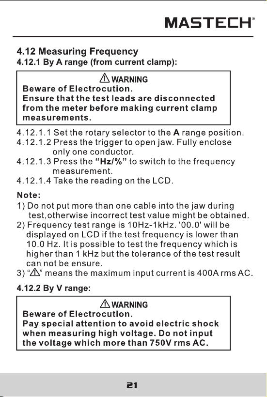
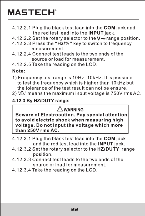
4.3 Switching Frequency or Duty
4.3.1 During working at the voltage or current ranges,
press the “Hz/%” button one time, frequency of
the voltage or current will be measured. Press the
“Hz/%” button twice, the meter will be changed
into the duty range for measuring the duty cycle of
the voltage or current. At the same time, the meter
is changed into manual mode.
4.3.2 Press the “Hz/%” button again, meter will be back
to the condition of the voltage or current measuring.
Note:
During working at maximum or minimum value
measuring function, the meter can't be changed into
frequency or duty cycle measuring mode.
4.4 Switching Maximum or Minimum Value
4.4.1 At all ranges, press the “MAX/MIN” button
one time, the meter can be set to maximum
value measuring mode; press the button twice,
the meter can be set to minimum value
measuring mode; press the button three times,
the meter will get back to normal test mode, and
the maximum and minimum value will be
recorded by the chip.
4.4.2 Press the “MAX/MIN” button more than two
second , the meter will get back to normal test.
1) During measuring maximum or minimum value, the
meter will be set to manual mode automatically.
2) During working at frequency or duty measuring
function, the meter can't be changed into maximum
or minimum value measuring mode.
Note:
4.5 Switching Functions
1) SELECT Key is a function selection key that acts
with trigger. Press the key can choose the needed
measurement mode: To choose DC or AC in DC/AC
status, to choose Diode or Buzzer in Diode/Buzzer
status, to choose Ohm, Cap, Diode or Buzzer in
Ohm/Cap/Diode/ Buzzer status.
2) Press the key then turn on the power, the Auto
Power-off function will be cancelled, the signal “ ”
disappears in LCD, and enter into Sleep Status
(Power-Off). Press the key then power on will have
the Auto Power-Off function.

15
16
4. Operation Instruction
4.1.1 Press the “HOLD/B.L” button to hold the readings
while taking measurement and the value on the
display will be held.
4.1.2 Press the “HOLD/B.L” button again to release the
reading hold function.
4.1 Holding Readings
4.2 SWitching Manual or Auto Mode
Range key is the Auto/Manual measurement key
that acts with trigger. Auto measurement is
pre-set as power-on, and switches to Manual
measurement when the key is pressed one time.
In Manual measurement mode, mode will move
upward upon each press to the highest mode,
then return to the lowest mode as a loop. If press
the key over 2 seconds, the system will switch
back to Auto measurement status.
4.3 Switching Frequency or Duty
4.3.1 During working at the voltage or current ranges,
press the “Hz/%” button one time, frequency of
the voltage or current will be measured. Press the
“Hz/%” button twice, the meter will be changed
into the duty range for measuring the duty cycle of
the voltage or current. At the same time, the meter
is changed into manual mode.
4.3.2 Press the “Hz/%” button again, meter will be back
to the condition of the voltage or current measuring.
Note:
During working at maximum or minimum value
measuring function, the meter can't be changed into
frequency or duty cycle measuring mode.
4.4 Switching Maximum or Minimum Value
4.4.1 At all ranges, press the “MAX/MIN” button
one time, the meter can be set to maximum
value measuring mode; press the button twice,
the meter can be set to minimum value
measuring mode; press the button three times,
the meter will get back to normal test mode, and
the maximum and minimum value will be
recorded by the chip.
4.4.2 Press the “MAX/MIN” button more than two
second , the meter will get back to normal test.
1) During measuring maximum or minimum value, the
meter will be set to manual mode automatically.
2) During working at frequency or duty measuring
function, the meter can't be changed into maximum
or minimum value measuring mode.
Note:
4.5 Switching Functions
1) SELECT Key is a function selection key that acts
with trigger. Press the key can choose the needed
measurement mode: To choose DC or AC in DC/AC
status, to choose Diode or Buzzer in Diode/Buzzer
status, to choose Ohm, Cap, Diode or Buzzer in
Ohm/Cap/Diode/ Buzzer status.
2) Press the key then turn on the power, the Auto
Power-off function will be cancelled, the signal “ ”
disappears in LCD, and enter into Sleep Status
(Power-Off). Press the key then power on will have
the Auto Power-Off function.
19
20
1) Do not put more than one cable into the jaw during test,
otherwise incorrect test value might be obtained.
2) For optimum results, center the conductor in the jaw.
3) At the manual range mode, when only 'OL' is shown on
the LCD, it means the measurement has exceeded the
range. A higher range should be selected.
4) If the scale of the value to be measured is unknown
beforehand, set the range to the highest.
5) “ ” means the maximum input current is 1000A rms AC.
4.11 Measuring DC Voltage
4.10 Measuring AC Voltage
Note:
Beware of Electrocution.
Pay special attention to avoid electric shock
when measuring high voltage.
Do not input the voltage which more than 600V
rms AC.
WARNING
4.10.1 Plug the black test lead into the COM jack and the
red test lead into the INPUT jack.
4.10.2 Set the rotary selector to position to make the
meter get into AC V range.
4.10.3 Connect the test leads to the voltage source or
load terminals for measurement.
4.10.5 Take the reading on the LCD.
V
Note:
1) “ ”means the maximum input voltage is 750V rms AC.
2) If the test result is more than 750V rms AC, symbol
“OL” will be displayed on LCD and the build-up buzzer
will sound.
Beware of Electrocution.
Pay special attention to avoid electric shock
when measuring high voltage.
Do not input the voltage which more than
600V DC.
WARNING
4.11.1 Plug the black test lead into the COM jack and
the red test lead into the INPUT jack.
4.11.2 Set the rotary selector to at the range position.
4.11.3 Connect the test leads to the voltage source or
load terminals for measurement.
4.11.4 Take the reading on the LCD. The polarity
symbol denotes the polarity of the end
connected by the red test lead.
V
Note:
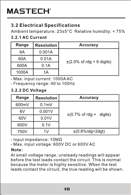
1) At small voltage range, unsteady readings will
appear before the test leads contact the circuit.
This is normal because the meter is highly sensitive.
When the test leads contact the circuit, the true
reading will be shown.
2) “ ” means the maximum input voltage is 600V DC.
3) If the test result is more than 1000V DC, symbol
“OL” will be displayed on LCD and the build-up
buzzer will sound.
19
20
1) Do not put more than one cable into the jaw during test,
otherwise incorrect test value might be obtained.
2) For optimum results, center the conductor in the jaw.
3) At the manual range mode, when only 'OL' is shown on
the LCD, it means the measurement has exceeded the
range. A higher range should be selected.
4) If the scale of the value to be measured is unknown
beforehand, set the range to the highest.
5) “ ” means the maximum input current is 1000A rms AC.
4.11 Measuring DC Voltage
4.10 Measuring AC Voltage
Note:
Beware of Electrocution.
Pay special attention to avoid electric shock
when measuring high voltage.
Do not input the voltage which more than 600V
rms AC.
WARNING
4.10.1 Plug the black test lead into the COM jack and the
red test lead into the INPUT jack.
4.10.2 Set the rotary selector to position to make the
meter get into AC V range.
4.10.3 Connect the test leads to the voltage source or
load terminals for measurement.
4.10.5 Take the reading on the LCD.
V
Note:
1) “ ”means the maximum input voltage is 750V rms AC.
2) If the test result is more than 750V rms AC, symbol
“OL” will be displayed on LCD and the build-up buzzer
will sound.
Beware of Electrocution.
Pay special attention to avoid electric shock
when measuring high voltage.
Do not input the voltage which more than
600V DC.
WARNING
4.11.1 Plug the black test lead into the COM jack and
the red test lead into the INPUT jack.
4.11.2 Set the rotary selector to at the range position.
4.11.3 Connect the test leads to the voltage source or
load terminals for measurement.
4.11.4 Take the reading on the LCD. The polarity
symbol denotes the polarity of the end
connected by the red test lead.
V
Note:
1) At small voltage range, unsteady readings will
appear before the test leads contact the circuit.
This is normal because the meter is highly sensitive.
When the test leads contact the circuit, the true
reading will be shown.
2) “ ” means the maximum input voltage is 600V DC.
3) If the test result is more than 1000V DC, symbol
“OL” will be displayed on LCD and the build-up
buzzer will sound.

25
26
4.13.3.1 Plug the black test lead into the COM jack and
the red test lead into the INPUT jack.
4.13.2.2 Set the rotary selector to the HZ/DUTY range
position.
4.13.2.3 Press the “Hz/%” to switch to DUTY
measurement.
4.13.2.4 Connect test leads to the two end of the source
or load for measurement.
4.13.2.5 Take the reading on the LCD.
Note:
1) If the duty cycle is less than 10%, symbol 'UL' will be
displayed on LCD; if the duty cycle is more than
99.9%, symbol 'OL' will be displayed on LCD.
4.14 Measuring Resistance
Beware of Electrocution.
When measuring in-circuit resistance, make
sure that the power of the circuit under test
has been turned off and that all capacitors
have been fully discharged.
WARNING
4.14.1 Plug the black test lead into the COM jack and the
red test lead into the INPUT jack.
4.14.2 Set the rotary selector to the range position to
make the meter get into Ω range.
4.14.3 Connect the test leads to the ends of the resistor
or circuit for measurement.
4.14.4 Take the reading on the LCD.
Note:
1) When the input is open, 'OL' will appear on the LCD to
indicate that the range has been exceeded.
2) For measuring resistance above 1MΩ, it may take a
few seconds to get a steady reading. This is normal
for high resistance reading.
Ω
4.13.3 By HZ/DUTY range:
Beware of Electrocution. Pay special attention
to avoid electric shock when measuring high
voltage. Do not input the voltage which more
than 250V rms AC.
WARNING
5
5

29
30
Note:
1. It may take some time (about 30 seconds for the 400μF
and 4000μF range) for steady readings when
measuring high capacity.
4.17 Measuring Capacitance
Beware of Electrocution.
To avoid electric shock, make sure that the
capacitors have been fully discharged before
measuring the capacitance of a capacitor.
WARNING
4.17.1 Plug the black test lead into the COM jack and
the red test lead into the INPUT jack.
4.17.2 Set the rotary selector to the range position.
4.17.3 After fully discharged the capacitor, connect the
test leads to the two ends of the capacitor for
measurement.
4.18.4 Take the reading on the LCD.
Ω
5. Maintenance
Replace test leads if leads become damaged or worn.
Use meet EN 61010-031 standard, rated CAT III 600V, or
better test leads.
WARNING
5.1 Replacing The Batteries
WARNING
To avoid electric shock, make sure that the test
leads have been clearly move away from the
circuit under measurement before opening the
battery cover of the meter.
5.1.1 If the sign “ ” appears, it means that the
batteries should be replaced.
5.1.2 Loosen the fixing screw of the battery cover and
remove it.
5.1.3 Replace the exhausted batteries with new ones.
5.1.4 Put the battery cover back and fix it again to its
origin form.
Note:
Do not reverse the polarity of the batteries.
WARNING
Do not mix old and new batteries. Do not mix
alkaline, standard (carbon-zinc), or rechargeable
(ni-cad, ni-mh, etc) batteries.
5.2 Replacing Test Leads

31
00-05-3033
6. Accessories
1) Test Leads: Electric Ratings 1000V 10A 1 pair (set)
2) Operating Manual 1 copy
3) 1.5V AAA Battery 3 piece

31
00-05-3033
6. Accessories
1) Test Leads: Electric Ratings 1000V 10A 1 pair (set)
2) Operating Manual 1 copy
3) 1.5V AAA Battery 3 piece