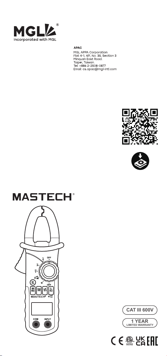
MS2108
DIGITAL CLAMP METER
OPERATION MANUAL
Hz
AUTO
MANU
MAX MIN
ZERO
°C°F%
μmVA
nμmF
MkΩ
INRU SH
TRMS
AC/DC CLAMP METER INRUSH
T-RMS
AUTO-PWER OFF
Press 2 Sec
MS2108
Ω
A
V
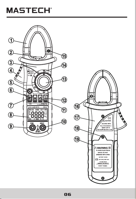
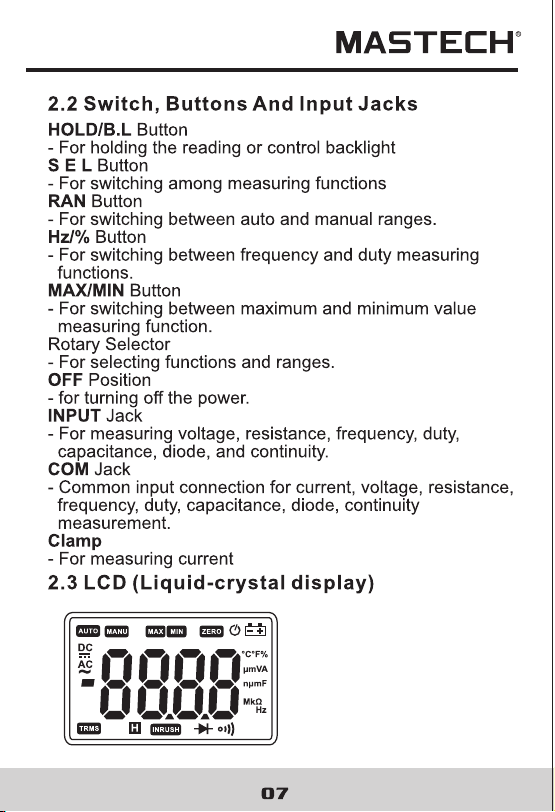
COM
INPUT
CAT III
MAX600V
600V
B.L
HOLD
Hz/%
RAN
MIN
MAX
SEL
A
OFF
600V CAT lll
MAX 600A
OFF

1.1 Preliminary
1.2 During use
1.3 Symbols............
CONTENTS CONTENTS
1. Safety Information
............................1
............................................1
...................................2
.............................4
4
............7
..................................7
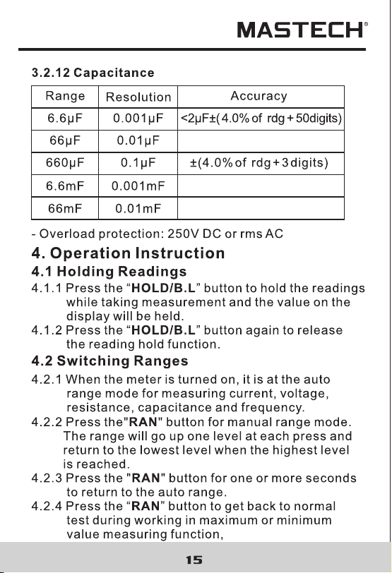
.......................15
.................................15
.................................15
................16
....................................16
....................................3
..............................17
...
....
..
1.4 Maintenance............
2. Description
.......................................
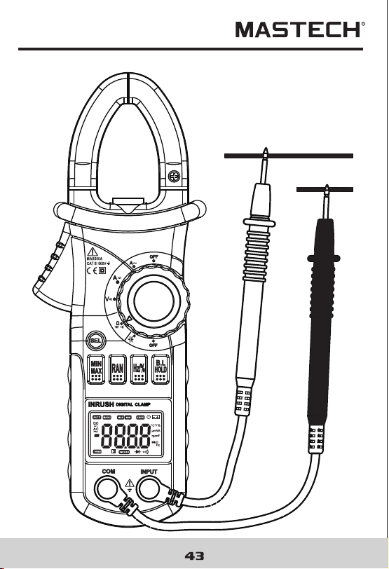
2.1 Names OF Parts
....................................6
2.2 Switch, Buttons And Input Jacks
2.3 Names OF Parts
3. Specifications
..................................11
4. Operation Instruction
........................11
3.1 General Specifications
3.2 Technical Specifications
......................12
4.1 Holding Readings
4.2 Switching Ranges
4.3 Switching Frequency Or Duty
4.4 Switching Maximum Or
Minimum Value
4.5 Switching Functions
4.6 Back Light And Clamp Lighting Bulb
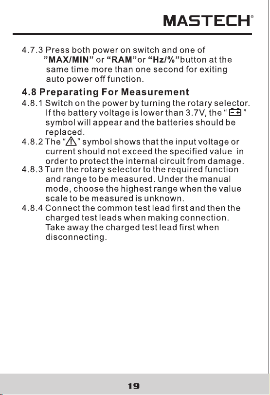
4.7 Auto Power Off..........................................18
4.8 Preparing For Measurement
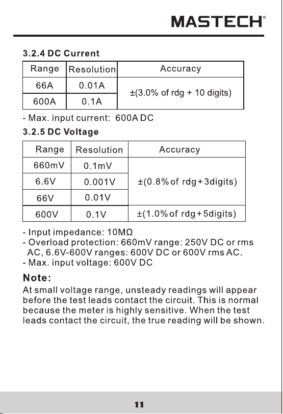
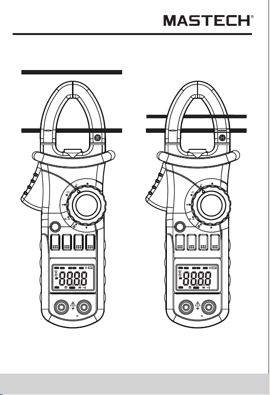
4.9 Measuring Ac Current
4.10 Measuring Inrush Current
4.11 Measuring Dc Current
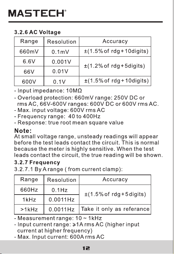
4.12 Measuring Ac Voltage
4.13 Measuring Dc Voltage
......................19
...............................20
........................22
..............................24
..............................26
..............................27
..............................30
.......................................34
.............................38
..........................................40
....................................42
...........................44
.......17
4.14 Measuring Frequency
4.15 Measuring Duty
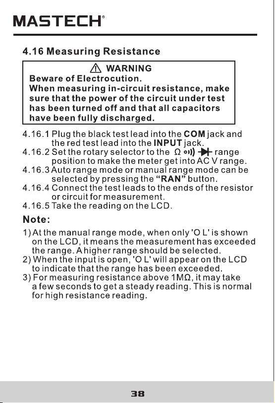
4.16 Measuring Resistance
4.17 Testing Diode
4.18 Testing Continuity
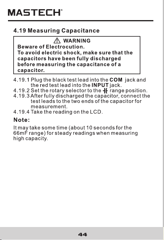
4.19 Measuring Capacitance
5. Maintenance
.......................................46
.............................46
5.1 Replacing The Batteries
5.2 Replacing Test Leads
.................................46
6. Accessories
.......................................46
1.1 Preliminary
1.2 During use
1.3 Symbols............
CONTENTS CONTENTS
1. Safety Information
............................1
............................................1
...................................2
.............................4
4
............7
..................................7
.......................15
.................................15
.................................15
................16
....................................16
....................................3
..............................17
...
....
..
1.4 Maintenance............
2. Description
.......................................
2.1 Names OF Parts
....................................6
2.2 Switch, Buttons And Input Jacks
2.3 Names OF Parts
3. Specifications
..................................11
4. Operation Instruction
........................11
3.1 General Specifications
3.2 Technical Specifications
......................12
4.1 Holding Readings
4.2 Switching Ranges
4.3 Switching Frequency Or Duty
4.4 Switching Maximum Or
Minimum Value
4.5 Switching Functions
4.6 Back Light And Clamp Lighting Bulb
4.7 Auto Power Off..........................................18
4.8 Preparing For Measurement
4.9 Measuring Ac Current
4.10 Measuring Inrush Current
4.11 Measuring Dc Current
4.12 Measuring Ac Voltage
4.13 Measuring Dc Voltage
......................19
...............................20
........................22
..............................24
..............................26
..............................27
..............................30
.......................................34
.............................38
..........................................40
....................................42
...........................44
.......17
4.14 Measuring Frequency
4.15 Measuring Duty
4.16 Measuring Resistance
4.17 Testing Diode
4.18 Testing Continuity
4.19 Measuring Capacitance
5. Maintenance
.......................................46
.............................46
5.1 Replacing The Batteries
5.2 Replacing Test Leads
.................................46
6. Accessories
.......................................46
03 04
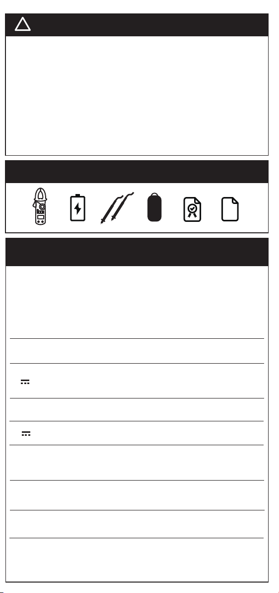
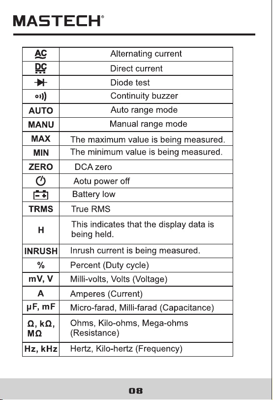
1.3 Symbols
Caution, risk of danger (Important safety
information; refer to the operation manual.)
Application around and removal from HAZARDOUS
LIVE conductors is permitted.
Double insulation(Protection class II).
Conforms to European Union Directive
Earth (ground) terminal
1.4 Maintenance
1.4.1 Do not attempt to remove the rear case to adjust
or repair the meter. Such actions should only be
performed by a technician who fully understands
the meter and the danger involved.
1.4.2 Before opening the case and battery cover of the
meter, always disconnect test leads from all
sources of electric current. Disconnect the test
leads from all sources of electric current before
1.2.11 Do not use the meter near explosive gases,
steam or dirt.
1.2.12 Stop using the meter if any abnormalities or
faults are observed.
1.2.13 Do not use the meter unless its rear case and
battery cover is securely fastened in its original
position.
1.2.14 Do not store or use the meter in areas exposed
to direct sunlight, at high temperature or with
high relative humidity.
CAT III Overvoltage (Installation) category III, Pollution
Degree 2 per IEC1010-1 refers to the level of
Impulse Withstand Voltage protection provided.
opening the rear case and battery cover of the meter.
1.4.3 To avoid any electric shock caused by error
readings, replace the batteries immediately when
the “ ” sign appears on the display.
1.4.4 Use damp cloth and mild detergent to clean the
meter; do not use abrasives or solvents.
1.4.5 Turn the rotary selector to OFF position to switch
off the power when the meter is not in use.
1.4.6 Remove the batteries to avoid damages to the
meter if it will idle for a long time.
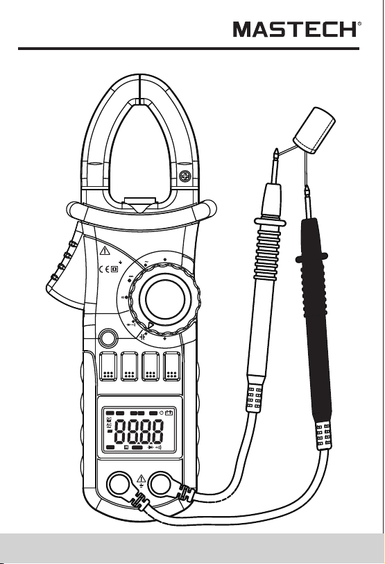
2. Description
- This meter is a portable professional measuring instrument
with LCD and back light easily reading. The 'single-hand
operation' design for the range switch makes measurement
simple and easy. Overload protection and low battery
indication are provided. It is an ideal multi-function
Instrument with scores of practical applications for
professional, workshop, school, hobby and home use.
- The meter can perform measurements of AC/DC voltage
and current, resistance, frequency, duty, capacitance, as
well as continuity and diode test.
- Both auto range and manual range are available.
- This meter is equipped with reading hold function.
- This meter is equipped with true root mean square value
measuring function (at AC A and AC V range).
- This meter is equipped with inrush current measuring
function.
- This meter is equipped with auto zero function
(at DCA range).
- This meter is equipped with maximum value measuring
function.
- This meter is equipped with minimum value measuring
function.
- This meter can measure frequency by clamp.
- This meter has function of auto power off.

03 04
1.3 Symbols
Caution, risk of danger (Important safety
information; refer to the operation manual.)
Application around and removal from HAZARDOUS
LIVE conductors is permitted.
Double insulation(Protection class II).
Conforms to European Union Directive
Earth (ground) terminal
1.4 Maintenance
1.4.1 Do not attempt to remove the rear case to adjust
or repair the meter. Such actions should only be
performed by a technician who fully understands
the meter and the danger involved.
1.4.2 Before opening the case and battery cover of the
meter, always disconnect test leads from all
sources of electric current. Disconnect the test
leads from all sources of electric current before
1.2.11 Do not use the meter near explosive gases,
steam or dirt.
1.2.12 Stop using the meter if any abnormalities or
faults are observed.
1.2.13 Do not use the meter unless its rear case and
battery cover is securely fastened in its original
position.
1.2.14 Do not store or use the meter in areas exposed
to direct sunlight, at high temperature or with
high relative humidity.
CAT III Overvoltage (Installation) category III, Pollution
Degree 2 per IEC1010-1 refers to the level of
Impulse Withstand Voltage protection provided.
opening the rear case and battery cover of the meter.
1.4.3 To avoid any electric shock caused by error
readings, replace the batteries immediately when
the “ ” sign appears on the display.
1.4.4 Use damp cloth and mild detergent to clean the
meter; do not use abrasives or solvents.
1.4.5 Turn the rotary selector to OFF position to switch
off the power when the meter is not in use.
1.4.6 Remove the batteries to avoid damages to the
meter if it will idle for a long time.
2. Description
- This meter is a portable professional measuring instrument
with LCD and back light easily reading. The 'single-hand
operation' design for the range switch makes measurement
simple and easy. Overload protection and low battery
indication are provided. It is an ideal multi-function
Instrument with scores of practical applications for
professional, workshop, school, hobby and home use.
- The meter can perform measurements of AC/DC voltage
and current, resistance, frequency, duty, capacitance, as
well as continuity and diode test.
- Both auto range and manual range are available.
- This meter is equipped with reading hold function.
- This meter is equipped with true root mean square value
measuring function (at AC A and AC V range).
- This meter is equipped with inrush current measuring
function.
- This meter is equipped with auto zero function
(at DCA range).
- This meter is equipped with maximum value measuring
function.
- This meter is equipped with minimum value measuring
function.
- This meter can measure frequency by clamp.
- This meter has function of auto power off.

09 10
3. Specifications
Calibration is required once a year, to be carried out at
a temperature between 18°C and 28°C (64°F to 82°F)
and relative humidity below 75%.
3.1 General Specifications
3.1.1 Auto range and manual range options are available.
3.1.2 Over range protection is provided for all ranges.
3.1.3 Maximum voltage between terminals and earth
ground: 600V DC or rms AC
3.1.4 Operating altitude: max. 2000 meters (7000 ft.)
3.1.5 Display: LCD
3.1.6 Maximum value display: 6599 digits
3.1.7 Polarity indication: automatic; ‘-’ for negative
polarity.
3.1.8 Over range indication: ‘0L’ or ‘-0L’
3.1.9 Sampling Time: approx. 0.4 second per sample
3.1.10 Unit indication: function and unit.
3.1.11 Auto power off time: 30 min.
3.1.12 Operating power : 1.5V×3 AAA batteries
3.1.13 Battery low indication: ‘ ’ on LCD
3.1.14 Temperature factor: < 0.1×Accuracy /°C
3.1.15 Operating temperature: 0°C to 40°C(32°F to 104°F)
3.1.16 Storage temperature: -10°C to 50°C(10°F to 122°F)
3.1.17 Dimension: 208×78×35mm
3.1.18 Weight: approximate 340g(including batteries)
3.2 Electrical Specifications
Ambient temperature: 23±5°C Relative humidity: < 75%
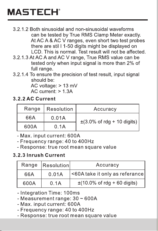
3.2.1 TRUE RMS
3.2.1.1 For measuring non-sinusoidal waveforms, test
error which is occurred by using True RMS
measurement techniques is less than by using
traditional average-reading techniques.
09 10
3. Specifications
Calibration is required once a year, to be carried out at
a temperature between 18°C and 28°C (64°F to 82°F)
and relative humidity below 75%.
3.1 General Specifications
3.1.1 Auto range and manual range options are available.
3.1.2 Over range protection is provided for all ranges.
3.1.3 Maximum voltage between terminals and earth
ground: 600V DC or rms AC
3.1.4 Operating altitude: max. 2000 meters (7000 ft.)
3.1.5 Display: LCD
3.1.6 Maximum value display: 6599 digits
3.1.7 Polarity indication: automatic; ‘-’ for negative
polarity.
3.1.8 Over range indication: ‘0L’ or ‘-0L’
3.1.9 Sampling Time: approx. 0.4 second per sample
3.1.10 Unit indication: function and unit.
3.1.11 Auto power off time: 30 min.
3.1.12 Operating power : 1.5V×3 AAA batteries
3.1.13 Battery low indication: ‘ ’ on LCD
3.1.14 Temperature factor: < 0.1×Accuracy /°C
3.1.15 Operating temperature: 0°C to 40°C(32°F to 104°F)
3.1.16 Storage temperature: -10°C to 50°C(10°F to 122°F)
3.1.17 Dimension: 208×78×35mm
3.1.18 Weight: approximate 340g(including batteries)
3.2 Electrical Specifications
Ambient temperature: 23±5°C Relative humidity: < 75%
3.2.1 TRUE RMS
3.2.1.1 For measuring non-sinusoidal waveforms, test
error which is occurred by using True RMS
measurement techniques is less than by using
traditional average-reading techniques.
13 14
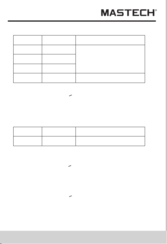
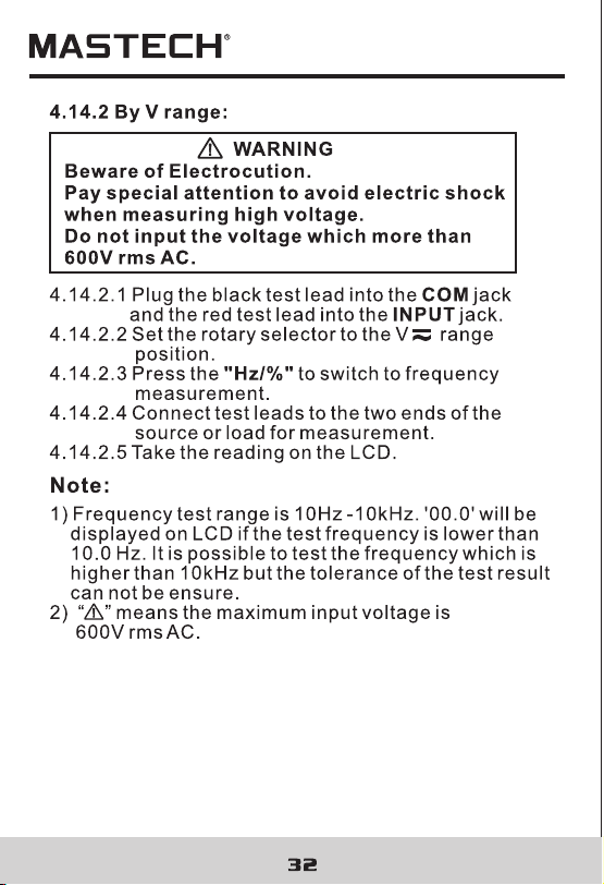
3.2.7.2 By V range:
Accuracy
Resolution
0.1Hz
0.001kHz
Range
660Hz
6.6kHz
0.01kHz 10kHz
>10kHz
Take it only as referance
±(1.5% of rdg + 5 digits)
- Measurement range: 10 ~ 10kHz
- Input voltage range:>0.2V rms AC (higher input
voltage at higher frequency)
- Input impedance: 10MΩ
- Max. input voltage: 600V rms AC
3.2.8 Duty Cycle
Accuracy
Resolution
0.1%
Range
10 - 95% ±3.0%
3.2.8.1 By A range ( from current clamp):
- Frequency response: 10 ~1kHz
- Input current range:>1A rms AC (higher input current
at higher frequency)
- Max. input current: 600A
3.2.8.2 By V range:
- Frequency response: 10 ~ 10 kHz
- Input voltage range:>0.2V rms AC (higher input
voltage at higher frequency)
- Input impedance: 10MΩ
- Max. input voltage: 600V rms AC
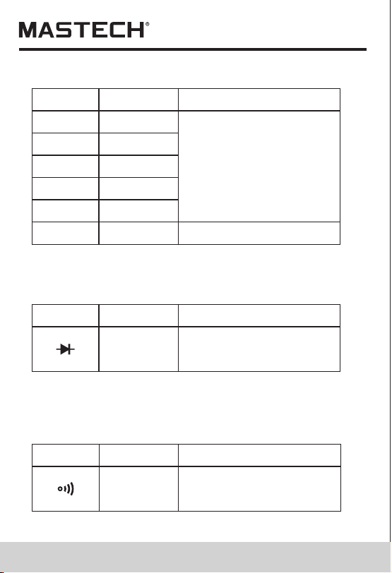
Accuracy
Resolution
0.1Ω
0.001kΩ
Range
660Ω
6.6kΩ
0.01kΩ 66KΩ
0.1kΩ
660kΩ
±(1.2% of rdg + 2digits)
0.001MkΩ 6.6MΩ
0.1MΩ66MΩ
- Open circuit voltage: 0.4V
- Overload protection: 250V DC or rms AC
3.2.9 Resistance
±(2.0% of rdg + 5digits)
3.2.10 Diode
Function
Resolution
Range
displaying approximate
forward voltage of diode
0.001V
- Forward DC current~1mA
- Reversed DC voltage~3.3V
- Overload protection: 250V DC or rms AC
Resolution
Range
Built-in buzzer will sound,
if resistance is lower than
30.
0.1Ω
- Open circuit voltage~1.2V
- Overload protection: 250V DC or rms AC
3.2.11 Continuity
0.01kHz
Function
13 14
3.2.7.2 By V range:
Accuracy
Resolution
0.1Hz
0.001kHz
Range
660Hz
6.6kHz
0.01kHz 10kHz
>10kHz
Take it only as referance
±(1.5% of rdg + 5 digits)
- Measurement range: 10 ~ 10kHz
- Input voltage range:>0.2V rms AC (higher input
voltage at higher frequency)
- Input impedance: 10MΩ
- Max. input voltage: 600V rms AC
3.2.8 Duty Cycle
Accuracy
Resolution
0.1%
Range
10 - 95% ±3.0%
3.2.8.1 By A range ( from current clamp):
- Frequency response: 10 ~1kHz
- Input current range:>1A rms AC (higher input current
at higher frequency)
- Max. input current: 600A
3.2.8.2 By V range:
- Frequency response: 10 ~ 10 kHz
- Input voltage range:>0.2V rms AC (higher input
voltage at higher frequency)
- Input impedance: 10MΩ
- Max. input voltage: 600V rms AC
Accuracy
Resolution
0.1Ω
0.001kΩ
Range
660Ω
6.6kΩ
0.01kΩ 66KΩ
0.1kΩ
660kΩ
±(1.2% of rdg + 2digits)
0.001MkΩ 6.6MΩ
0.1MΩ66MΩ
- Open circuit voltage: 0.4V
- Overload protection: 250V DC or rms AC
3.2.9 Resistance
±(2.0% of rdg + 5digits)
3.2.10 Diode
Function
Resolution
Range
displaying approximate
forward voltage of diode
0.001V
- Forward DC current~1mA
- Reversed DC voltage~3.3V
- Overload protection: 250V DC or rms AC
Resolution
Range
Built-in buzzer will sound,
if resistance is lower than
30.
0.1Ω
- Open circuit voltage~1.2V
- Overload protection: 250V DC or rms AC
3.2.11 Continuity
0.01kHz
Function

- LED, which requires a larger working current, is the
main source of back light. Although the meter is
equipped with a timer set at 60 seconds (i.e. the back
light will be off automatically after 60 seconds),
frequent use of the back light will shorten the life of
the batteries. Therefore, do not use the back light
unless necessary.
-When the battery voltage is<3.7V, the symbol “”
(battery low)will appear on the LCD. When the back
light is on, even if the batter is>3.7V, the “” may
appear because of its large working current which
will cause the voltage to drop. (The accuracy
of the measurement cannot be assured when the
“ “ symbol appears.) In this case, you need not
replace the batteries yet. Normally, the batteries
can last until the “” appears when the back light
is not being used.
17 18
1) During measuring maximum or minimum value, the
meter will be set to manual mode automatically.
2) During working at frequency or duty measuring
function, the meter can't be changed into maximum
or minimum value measuring mode.
Note:
4.5 Switching Functions
4.5.1 AC A range
4.5.1.1 Press the “SEL” button, the meter will get
into inrush current test mode.
4.5.1.2 If press the “SEL” button again, the meter
will get into inrush current test mode again.
4.5.1.3 Press the “SEL” button more than one second
or press the “RAN”button, the meter will get
back to normal test mode.
4.5.2 DC A range
4.5.2.1 Press the “SEL” button, the meter will get
into zero.
4.5.2.2 If press the “SEL” button again, the meter
will get into zero again.
4.5.2.3 Press the “SEL” button more than one
second or press the “RAN” button, the meter
will get back to the normal test mode.
4.5.4 Press the ”SEL” button to switch among
resistance, diode and continuity ranges.
4.5.3 Press the “SEL” button to switch between AC
and DC measurement at the voltage ranges.
4.6 Back Light And Clamp Lighting Bulb
4.6.1 Press the “HOLD/B.L” button for two or more
seconds to switch on the back light if the light
in the environment is too dim for taking reading,
which will last for 60 seconds.
4.6.2 During the back light is working, press the
“HOLD/B.L” button for two or more seconds, it
will be turned off.
4.6.3 At the current range, when the back light is
switched on, the clamp lighting bulb will be turned
on at the same time.
Note:
4.7 Auto Power Off
4.7.1 If there is no any operation within any thirty
minutes after power is on, meter will auto power
off.
4.7.2 After auto power off, if press the “SEL” button,
meter will recover the working condition.
21 22
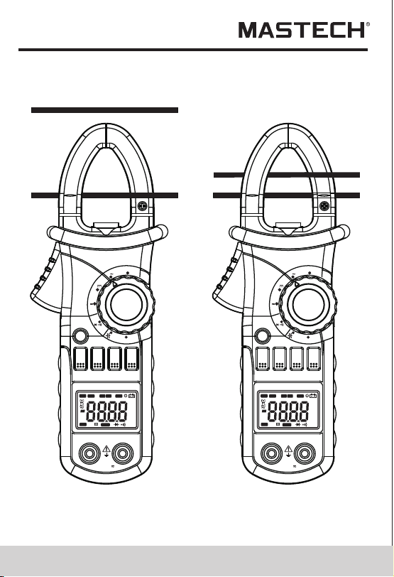
4.10 Measuring Inrush Current
WARNING
Beware of Electrocution.
Ensure that the test leads are disconnected
from the meter before making current clamp
measurements.
4.10.1 Set the rotary selector to the A range position.
4.10.2 Press the trigger to open jaw. Fully enclose
only one conductor.
4.10.3 Press the “SEL” to enter the INRUSH current
measurement mode. Then LCD displays
“- - - -” until the motor starting up and being
detected. The detection will be done only one
time and the output reading will be hold.
4.10.4 Take the reading on the LCD.
Note:
1) Do not put more than one cable into
the jaw during test, otherwise incorrect
test value might be obtained.
2) For optimum results, center the conductor in the jaw.
3) At the manual range mode, when only ‘O L’ is shown
on the LCD, it means the measurement has
exceeded the range. A higher range should
be selected.
4) Under the manual range mode, when the scale of
the value to be measured is unknown beforehand,
set the range to the highest.
5) “ ” means the maximum input current is
600A rms AC.
V
OFF
Ω
OFF
A
MAX
MIN
RAN
HOLD
B.L
Hz/%
SEL
INRUSH
DIGITALCLAMP
A
V
OFF
Ω
OFF
A
MAX
MIN
RAN
HOLD
B.L
Hz/%
SEL
INRUSH
DIGITALCLAMP
A
COM
INPUT
COM
INPUT
CAT.III
MAX600V
600V
CAT.III
MAX600V
600V
Hz
AUTO
MANU
MAX MIN
ZERO
°C°F%
μmVA
nμmF
MkΩ
INRU SH
TRMS
Hz
AUTO
MANU
MAX MIN
ZERO
°C°F%
μmVA
nμmF
MkΩ
INRU SH
TRMS
21 22
4.10 Measuring Inrush Current
WARNING
Beware of Electrocution.
Ensure that the test leads are disconnected
from the meter before making current clamp
measurements.
4.10.1 Set the rotary selector to the A range position.
4.10.2 Press the trigger to open jaw. Fully enclose
only one conductor.
4.10.3 Press the “SEL” to enter the INRUSH current
measurement mode. Then LCD displays
“- - - -” until the motor starting up and being
detected. The detection will be done only one
time and the output reading will be hold.
4.10.4 Take the reading on the LCD.
Note:
1) Do not put more than one cable into
the jaw during test, otherwise incorrect
test value might be obtained.
2) For optimum results, center the conductor in the jaw.
3) At the manual range mode, when only ‘O L’ is shown
on the LCD, it means the measurement has
exceeded the range. A higher range should
be selected.
4) Under the manual range mode, when the scale of
the value to be measured is unknown beforehand,
set the range to the highest.
5) “ ” means the maximum input current is
600A rms AC.
V
OFF
Ω
OFF
A
MAX
MIN
RAN
HOLD
B.L
Hz/%
SEL
INRUSH
DIGITALCLAMP
A
V
OFF
Ω
OFF
A
MAX
MIN
RAN
HOLD
B.L
Hz/%
SEL
INRUSH
DIGITALCLAMP
A
COM
INPUT
COM
INPUT
CAT.III
MAX600V
600V
CAT.III
MAX600V
600V
Hz
AUTO
MANU
MAX MIN
ZERO
°C°F%
μmVA
nμmF
MkΩ
INRU SH
TRMS
Hz
AUTO
MANU
MAX MIN
ZERO
°C°F%
μmVA
nμmF
MkΩ
INRU SH
TRMS
23 24
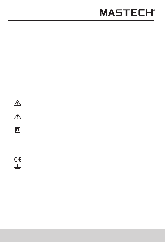
4.11 Measuring DC Current
WARNING
Beware of Electrocution.
Ensure that the test leads are disconnected
from the meter before making current clamp
measurements.
1) Do not put more than one cable into the jaw during
test, otherwise incorrect test value might be
obtained.
2) For optimum results, press the “SEL” button to
make the meter get into zero first.
3) For optimum results, center the conductor in the jaw.
4) At the manual range mode, when only 'O L' or '-O L'
is shown on the LCD, it means the measurement
has exceeded the range. A higher range should
be selected.
5) Under the manual range mode, when the scale
of the value to be measured is unknown beforehand,
set the range to the highest.
6) “ ”means the maximum input current is 600A DC.
4.11.1 Set the rotary selector to the A range position.
4.11.2 Auto range mode or manual range mode can be
selected by pressing the “RAN” button.
4.11.3 Press the “SEL” button, the meter will be set
to zero.
4.11.4 Press the trigger to open jaw. Fully enclose only
one conductor.
4.11.5 Take the reading on the LCD.
4.11.6 Symbol “-” will be displayed on LCD if the
direction of the current is negative.
Note:
V
OFF
Ω
OFF
A
MAX
MIN
RAN
HOLD
B.L
Hz/%
SEL
INRUSH
DIGITALCLAMP
A
V
OFF
Ω
OFF
A
MAX
MIN
RAN
HOLD
B.L
Hz/%
SEL
INRUSH
DIGITALCLAMP
A
COM
INPUT
COM
INPUT
CAT.III
MAX600V
600V
CAT.III
MAX600V
600V
Correct
Incorrect
Hz
AUTO
MANU
MAX MIN
ZERO
°C°F%
μmVA
nμmF
MkΩ
INRU SH
TRMS
Hz
AUTO
MANU
MAX MIN
ZERO
°C°F%
μmVA
nμmF
MkΩ
INRU SH
TRMS
23 24
4.11 Measuring DC Current
WARNING
Beware of Electrocution.
Ensure that the test leads are disconnected
from the meter before making current clamp
measurements.
1) Do not put more than one cable into the jaw during
test, otherwise incorrect test value might be
obtained.
2) For optimum results, press the “SEL” button to
make the meter get into zero first.
3) For optimum results, center the conductor in the jaw.
4) At the manual range mode, when only 'O L' or '-O L'
is shown on the LCD, it means the measurement
has exceeded the range. A higher range should
be selected.
5) Under the manual range mode, when the scale
of the value to be measured is unknown beforehand,
set the range to the highest.
6) “ ”means the maximum input current is 600A DC.
4.11.1 Set the rotary selector to the A range position.
4.11.2 Auto range mode or manual range mode can be
selected by pressing the “RAN” button.
4.11.3 Press the “SEL” button, the meter will be set
to zero.
4.11.4 Press the trigger to open jaw. Fully enclose only
one conductor.
4.11.5 Take the reading on the LCD.
4.11.6 Symbol “-” will be displayed on LCD if the
direction of the current is negative.
Note:
V
OFF
Ω
OFF
A
MAX
MIN
RAN
HOLD
B.L
Hz/%
SEL
INRUSH
DIGITALCLAMP
A
V
OFF
Ω
OFF
A
MAX
MIN
RAN
HOLD
B.L
Hz/%
SEL
INRUSH
DIGITALCLAMP
A
COM
INPUT
COM
INPUT
CAT.III
MAX600V
600V
CAT.III
MAX600V
600V
Correct
Incorrect
Hz
AUTO
MANU
MAX MIN
ZERO
°C°F%
μmVA
nμmF
MkΩ
INRU SH
TRMS
Hz
AUTO
MANU
MAX MIN
ZERO
°C°F%
μmVA
nμmF
MkΩ
INRU SH
TRMS

WARNING
Beware of Electrocution.
Pay special attention to avoid electric shock
when measuring high voltage.
Do not input the voltage which more than
600V rms AC.
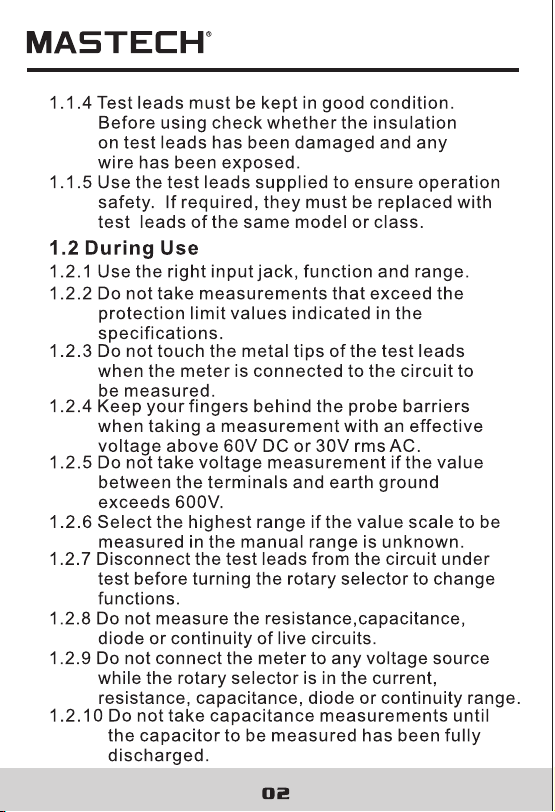
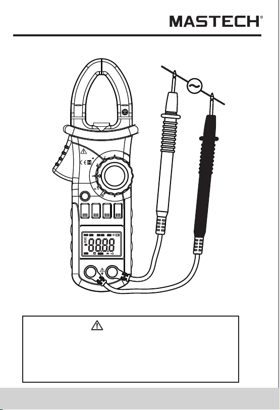
4.12 Measuring AC Voltage
4.12.1 Plug the black test lead into the COM jack and
the red test lead into the INPUT jack.
4.12.2 Set the rotary selector to V position to make
the meter get into AC V range.
4.12.3 Auto range mode or manual range mode can
be selected by pressing the “RAN” button.
4.12.4 Connect the test leads to the voltage source or
load terminals for measurement.
4.12.5 Take the reading on the LCD.
Note:
1) At small voltage range, unsteady readings may
appear before the test leads contact the circuit.
This is normal because the meter is highly sensitive.
When the test leads contact the circuit, the true
reading will be shown.
2) At the manual range mode, when only 'OL' is shown
on the LCD, it means the measurement has exceeded
the range. A higher range should be selected.
3) At the manual range mode, when the scale of the
value to be measured is unknown beforehand, select
the highest range first and lower the range gradually.
4) “ ” means the maximum input voltage is 600V rms AC.
5) If the test result is more than 610V rms AC, symbol
“OL” will be displayed on LCD and the build-up
buzzer will sound.
25 2 6
V
OFF
Ω
OFF
A
MAX
MIN
RAN
HOLD
B.L
Hz/%
SEL
INRUSH
DIGITALCLAMP
A
V
OFF
Ω
OFF
A
MAX
MIN
RAN
HOLD
B.L
Hz/%
SEL
INRUSH
DIGITALCLAMP
A
COM
INPUT
COM
INPUT
CAT.III
MAX600V
600V
CAT.III
MAX600V
600V
Correct
Incorrect
Hz
AUTO
MANU
MAX MIN
ZERO
°C°F%
μmVA
nμmF
MkΩ
INRU SH
TRMS
Hz
AUTO
MANU
MAX MIN
ZERO
°C°F%
μmVA
nμmF
MkΩ
INRU SH
TRMS

WARNING
Beware of Electrocution.
Pay special attention to avoid electric shock
when measuring high voltage.
Do not input the voltage which more than
600V rms AC.
4.12 Measuring AC Voltage
4.12.1 Plug the black test lead into the COM jack and
the red test lead into the INPUT jack.
4.12.2 Set the rotary selector to V position to make
the meter get into AC V range.
4.12.3 Auto range mode or manual range mode can
be selected by pressing the “RAN” button.
4.12.4 Connect the test leads to the voltage source or
load terminals for measurement.
4.12.5 Take the reading on the LCD.
Note:
1) At small voltage range, unsteady readings may
appear before the test leads contact the circuit.
This is normal because the meter is highly sensitive.
When the test leads contact the circuit, the true
reading will be shown.
2) At the manual range mode, when only 'OL' is shown
on the LCD, it means the measurement has exceeded
the range. A higher range should be selected.
3) At the manual range mode, when the scale of the
value to be measured is unknown beforehand, select
the highest range first and lower the range gradually.
4) “ ” means the maximum input voltage is 600V rms AC.
5) If the test result is more than 610V rms AC, symbol
“OL” will be displayed on LCD and the build-up
buzzer will sound.
25 2 6
V
OFF
Ω
OFF
A
MAX
MIN
RAN
HOLD
B.L
Hz/%
SEL
INRUSH
DIGITALCLAMP
A
V
OFF
Ω
OFF
A
MAX
MIN
RAN
HOLD
B.L
Hz/%
SEL
INRUSH
DIGITALCLAMP
A
COM
INPUT
COM
INPUT
CAT.III
MAX600V
600V
CAT.III
MAX600V
600V
Correct
Incorrect
Hz
AUTO
MANU
MAX MIN
ZERO
°C°F%
μmVA
nμmF
MkΩ
INRU SH
TRMS
Hz
AUTO
MANU
MAX MIN
ZERO
°C°F%
μmVA
nμmF
MkΩ
INRU SH
TRMS
27 28
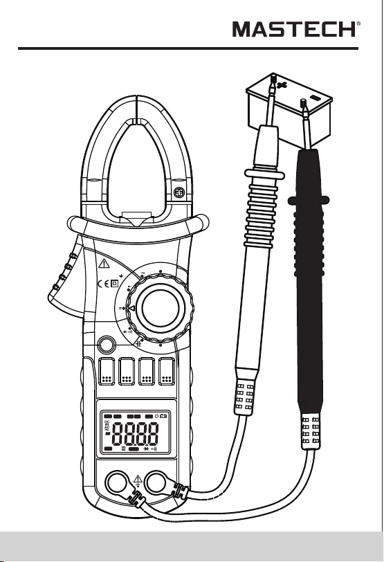
4.13 Measuring DC Voltage
WARNING
Beware of Electrocution.
Pay special attention to avoid electric shock
when measuring high voltage.
Do not input the voltage which more than
600V DC.
4.13.1 Plug the black test lead into the COM jack and
the red test lead into the INPUT jack.
4.13.2 Set the rotary selector to at the V range position.
4.13.3 Press the“SEL” button to turn to DC V range.
Auto range mode or manual range mode can be
selected by pressing the “RAN” button.
4.13.4 Connect the test leads to the voltage source or
load terminals for measurement.
4.13.5 Take the reading on the LCD. The polarity
symbol denotes the polarity of the end
connected by the red test lead.
Note:
1) At small voltage range, unsteady readings will
appear before the test leads contact the circuit.
This is normal because the meter is highly sensitive.
When the test leads contact the circuit, the true
reading will be shown.
2) Under the manual range mode, when only
‘O L ’ o r ‘- O L’ is shown on the LCD, it means the
measurement has exceeded the range. A higher
range should be selected.
3) Under the manual range mode, when the scale
of the value to be measured is unknown beforehand,
select the highest range first and lower the
range gradually.
4) “ ” means the maximum input voltage is 600V DC.
5) If the test result is more than 610V DC, symbol “O L”
will be displayed on LCD and the build-up buzzer
will sound.
MAX
MIN
RAN
HOLD
B.L
Hz/%
SEL
COM
INPUT
V
MIN 600A
CAT III 600V
OFF
A
A
OFF
Ω
INRUSH
DIGITALCLAMP
Hz
AUTO
MANU
MAX MIN
ZERO
°C°F%
μmVA
nμmF
MkΩ
INRUS H
TRMS

27 28
4.13 Measuring DC Voltage
WARNING
Beware of Electrocution.
Pay special attention to avoid electric shock
when measuring high voltage.
Do not input the voltage which more than
600V DC.
4.13.1 Plug the black test lead into the COM jack and
the red test lead into the INPUT jack.
4.13.2 Set the rotary selector to at the V range position.
4.13.3 Press the“SEL” button to turn to DC V range.
Auto range mode or manual range mode can be
selected by pressing the “RAN” button.
4.13.4 Connect the test leads to the voltage source or
load terminals for measurement.
4.13.5 Take the reading on the LCD. The polarity
symbol denotes the polarity of the end
connected by the red test lead.
Note:
1) At small voltage range, unsteady readings will
appear before the test leads contact the circuit.
This is normal because the meter is highly sensitive.
When the test leads contact the circuit, the true
reading will be shown.
2) Under the manual range mode, when only
‘O L ’ o r ‘- O L’ is shown on the LCD, it means the
measurement has exceeded the range. A higher
range should be selected.
3) Under the manual range mode, when the scale
of the value to be measured is unknown beforehand,
select the highest range first and lower the
range gradually.
4) “ ” means the maximum input voltage is 600V DC.
5) If the test result is more than 610V DC, symbol “O L”
will be displayed on LCD and the build-up buzzer
will sound.
MAX
MIN
RAN
HOLD
B.L
Hz/%
SEL
COM
INPUT
V
MIN 600A
CAT III 600V
OFF
A
A
OFF
Ω
INRUSH
DIGITALCLAMP
Hz
AUTO
MANU
MAX MIN
ZERO
°C°F%
μmVA
nμmF
MkΩ
INRUS H
TRMS
29 30
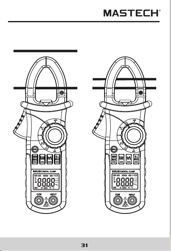
4.14 Measuring Frequency
4.14.1 By A range (from current clamp):
WARNING
Beware of Electrocution.
Ensure that the test leads are disconnected
from the meter before making current clamp
measurements.
4.14.1.1 Set the rotary selector to the A range
(A~ or A) position.
4.14.1.2 Press the trigger to open jaw. Fully enclose
only one conductor.
4.14.1.3 Press the “Hz/%” to switch to the frequency
measurement.
4.14.1.4 Take the reading on the LCD.
Note:
1) Do not put more than one cable into the jaw during
test, otherwise incorrect test value might be obtained.
2) Frequency test range is 10Hz - 1kHz.‘00.0’ will be
displayed on LCD if the test frequency is lower than
10.0 Hz. It is possible to test the frequency which is
higher than 1 kHz but the tolerance of the test result
can not be ensure.
3)“”means the maximum input current is
600A rms AC.
MAX
MIN
RAN
HOLD
B.L
Hz/%
SEL
COM
INPUT
V
MIN 600A
CAT III 600V
OFF
A
A
OFF
Ω
INRUSH
DIGITALCLAMP
9V
Hz
AUTO
MANU
MAX M IN
ZERO
°C°F%
μmVA
nμmF
MkΩ
INRU SH
TRMS
29 30
4.14 Measuring Frequency
4.14.1 By A range (from current clamp):
WARNING
Beware of Electrocution.
Ensure that the test leads are disconnected
from the meter before making current clamp
measurements.
4.14.1.1 Set the rotary selector to the A range
(A~ or A) position.
4.14.1.2 Press the trigger to open jaw. Fully enclose
only one conductor.
4.14.1.3 Press the “Hz/%” to switch to the frequency
measurement.
4.14.1.4 Take the reading on the LCD.
Note:
1) Do not put more than one cable into the jaw during
test, otherwise incorrect test value might be obtained.
2) Frequency test range is 10Hz - 1kHz.‘00.0’ will be
displayed on LCD if the test frequency is lower than
10.0 Hz. It is possible to test the frequency which is
higher than 1 kHz but the tolerance of the test result
can not be ensure.
3)“”means the maximum input current is
600A rms AC.
MAX
MIN
RAN
HOLD
B.L
Hz/%
SEL
COM
INPUT
V
MIN 600A
CAT III 600V
OFF
A
A
OFF
Ω
INRUSH
DIGITALCLAMP
9V
Hz
AUTO
MANU
MAX M IN
ZERO
°C°F%
μmVA
nμmF
MkΩ
INRU SH
TRMS
33 34
4.15 Measuring Duty
4.15.1 By A range ( from current clamp):
WARNING
Beware of Electrocution.
Ensure that the test leads are disconnected
from the meter before making current clamp
measurements.
4.15.1.1 Set the rotary selector to the A range
( A or A ) position.
4.15.1.2 Press the trigger to open jaw. Fully enclose
only one conductor.
4.15.1.3 Press the "Hz/%" to switch to the DUTY
measurement.
4.15.1.4 Take the reading on the LCD.
Note:
1) Do not put more than one cable into the jaw during
test, otherwise incorrect test value might be obtained.
2) If the duty cycle is less than 10%, symbol 'UL' will be
displayed on LCD; if the duty cycle is more than
94.9%, symbol 'O L' will be displayed on LCD.
3) The input signal frequency range is 10 – 1kHz. It is
possible to test duty cycle of the higher than 1 kHz
frequency signal, but the tolerance of the test result
can not be ensure.
4) “ ” means the maximum input current is
600A rms AC.
MAX
MIN
RAN
HOLD
B.L
Hz/%
SEL
COM
INPUT
V
MIN 600A
CAT III 600V
OFF
A
A
OFF
Ω
INRUSH
DIGITALCLAMP
Hz
AUTO
MANU
MAX MIN
ZERO
°C°F%
μmVA
nμmF
MkΩ
INRU SH
TRMS
35 36
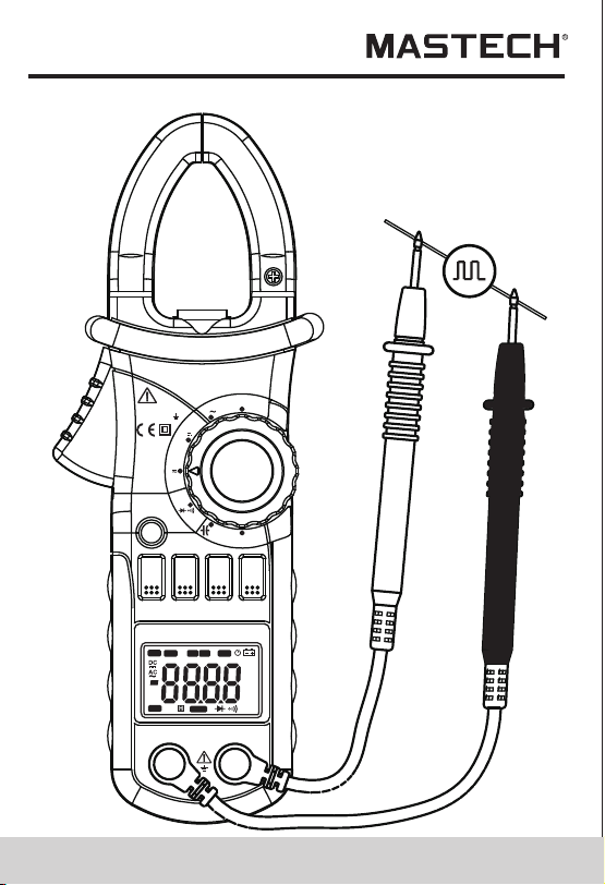
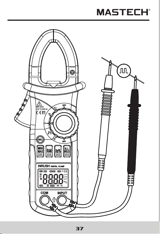
4.15.2 By V range:
WARNING
Beware of Electrocution.
Pay special attention to avoid electric shock
when measuring high voltage.
Do not input the voltage which more than
600V rms AC.
4.15.2.1 Plug the black test lead into the COM jack and
the red test lead into the INPUT jack.
4.15.2.2 Set the rotary selector to the V range position.
4.15.2.3 Press the "Hz/%" to switch to DUTY
measurement.
4.15.2.4 Connect test leads to the two end of the source
or load for measurement.
4.15.2.5 Take the reading on the LCD.
Note:
1) If the duty cycle is less than 10%, symbol 'UL' will be
displayed on LCD; if the duty cycle is more than
94.9%, symbol 'O L' will be displayed on LCD.
3) The input signal frequency range is 10 – 10 kHz. It is
possible to test duty cycle of the higher than 10 kHz
frequency signal, but the tolerance of the test result
can not be ensure.
3) “ ” means the maximum input voltage is
600V rms AC.
CAT.III
MAX600V
600V
CAT.III
MAX600V
600V
V
OFF
Ω
OFF
A
MAX
MIN
RAN
HOLD
B.L
Hz/%
SEL
INRUSH
DIGITALCLAMP
A
V
OFF
Ω
OFF
A
MAX
MIN
RAN
HOLD
B.L
Hz/%
SEL
INRUSH
DIGITALCLAMP
A
COM
INPUT
COM
INPUT
Correct
Incorrect
Hz
AUTO
MANU
MAX MIN
ZERO
°C°F%
μmVA
nμmF
MkΩ
INRU SH
TRMS
Hz
AUTO
MANU
MAX MIN
ZERO
°C°F%
μmVA
nμmF
MkΩ
INRU SH
TRMS
35 36
4.15.2 By V range:
WARNING
Beware of Electrocution.
Pay special attention to avoid electric shock
when measuring high voltage.
Do not input the voltage which more than
600V rms AC.
4.15.2.1 Plug the black test lead into the COM jack and
the red test lead into the INPUT jack.
4.15.2.2 Set the rotary selector to the V range position.
4.15.2.3 Press the "Hz/%" to switch to DUTY
measurement.
4.15.2.4 Connect test leads to the two end of the source
or load for measurement.
4.15.2.5 Take the reading on the LCD.
Note:
1) If the duty cycle is less than 10%, symbol 'UL' will be
displayed on LCD; if the duty cycle is more than
94.9%, symbol 'O L' will be displayed on LCD.
3) The input signal frequency range is 10 – 10 kHz. It is
possible to test duty cycle of the higher than 10 kHz
frequency signal, but the tolerance of the test result
can not be ensure.
3) “ ” means the maximum input voltage is
600V rms AC.
CAT.III
MAX600V
600V
CAT.III
MAX600V
600V
V
OFF
Ω
OFF
A
MAX
MIN
RAN
HOLD
B.L
Hz/%
SEL
INRUSH
DIGITALCLAMP
A
V
OFF
Ω
OFF
A
MAX
MIN
RAN
HOLD
B.L
Hz/%
SEL
INRUSH
DIGITALCLAMP
A
COM
INPUT
COM
INPUT
Correct
Incorrect
Hz
AUTO
MANU
MAX MIN
ZERO
°C°F%
μmVA
nμmF
MkΩ
INRU SH
TRMS
Hz
AUTO
MANU
MAX MIN
ZERO
°C°F%
μmVA
nμmF
MkΩ
INRU SH
TRMS
39 40
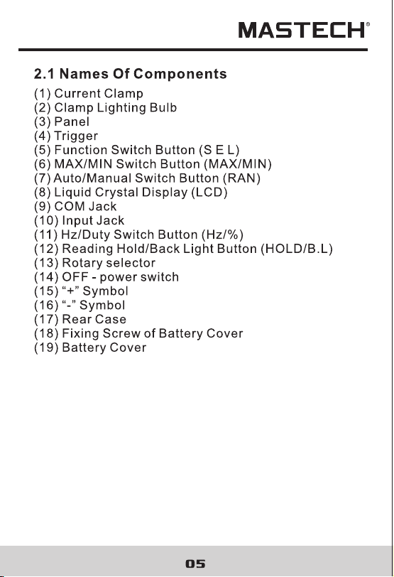
4.17 Testing Diode
4.17.1 Plug the black test lead into the COM jack and
the red test lead into the INPUT jack.
4.17.2 Set the rotary selector to the Ω range
position.
4.17.3 Press the "S E L" button to switch to test.
4.17.4 Connect the red test lead to the anode and the
black test lead to the cathode of the diode for
testing.
4.17.5 Take the reading on the LCD.
Note:
1) The meter will show the approximate forward voltage
drop of the diode.
2) When the test leads have been reversed or open,
'O L' will appear on the LCD.
V
OFF
Ω
OFF
A
A
INRUSH
DIGITALCLAMP
COM
INPUT
MAX600A
CAT III 600V
MAX
MIN
RAN
HOLD
B.L
Hz/%
SEL
Hz
AUTO
MANU
MAX MIN
ZERO
°C°F%
μmVA
nμmF
MkΩ
INRU SH
TRMS

39 40
4.17 Testing Diode
4.17.1 Plug the black test lead into the COM jack and
the red test lead into the INPUT jack.
4.17.2 Set the rotary selector to the Ω range
position.
4.17.3 Press the "S E L" button to switch to test.
4.17.4 Connect the red test lead to the anode and the
black test lead to the cathode of the diode for
testing.
4.17.5 Take the reading on the LCD.
Note:
1) The meter will show the approximate forward voltage
drop of the diode.
2) When the test leads have been reversed or open,
'O L' will appear on the LCD.
V
OFF
Ω
OFF
A
A
INRUSH
DIGITALCLAMP
COM
INPUT
MAX600A
CAT III 600V
MAX
MIN
RAN
HOLD
B.L
Hz/%
SEL
Hz
AUTO
MANU
MAX MIN
ZERO
°C°F%
μmVA
nμmF
MkΩ
INRU SH
TRMS
42
4.18 Testing Continuity
WARNING
Beware of Electrocution.
Make sure that the power of the circuit has
been turned off and the capacitors have been
fully discharged before testing the
continuity of a circuit.
4.18.1 Plug the black test lead into the COM jack and
the red test lead into the INPUT jack.
4.18.2 Set the rotary selector to the Ω range
position.
4.18.3 Press the "S E L" button to switch to continuity
test.
4.18.4 Connect the test leads to the two ends of the
circuit for measurement.
4.18.5 If the resistance of the circuit being tested is less
than 30Ω, the built-in buzzer will sound.
4.18.6 Take the reading on the LCD.
Note:
If the test leads are open or the resistance of the circuit
is over 660Ω , “O L” will appear on the LCD.
41
V
OFF
Ω
OFF
A
A
INRUSH
DIGITALCLAMP
COM
INPUT
MAX600A
CAT III 600V
MAX
MIN
RAN
HOLD
B.L
Hz/%
SEL
Hz
AUTO
MANU
MAX MIN
ZERO
°C°F%
μmVA
nμmF
MkΩ
INRU SH
TRMS
46
5. Maintenance
45
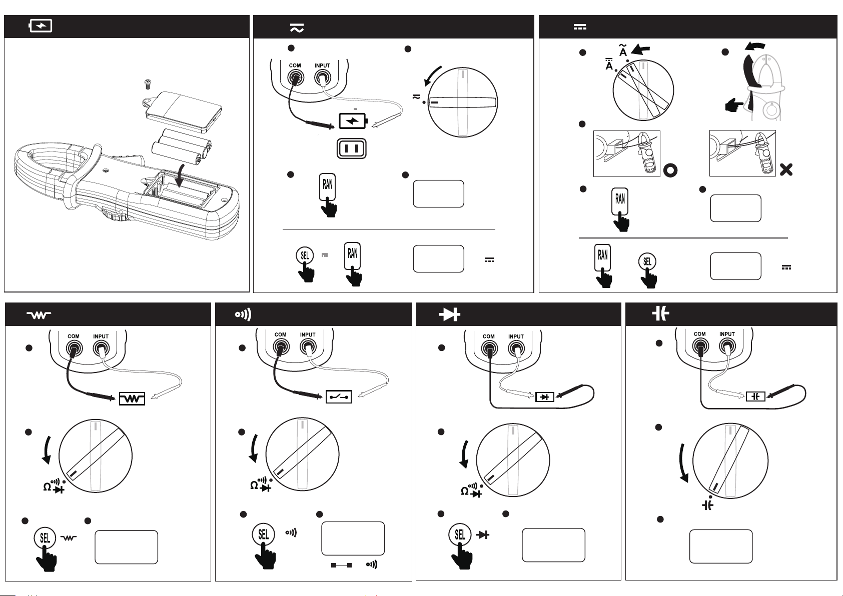
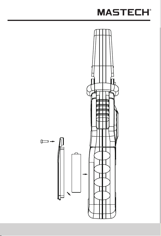
5.1 Replacing The Batteries
WARNING
To avoid electric shock, make sure that the
test leads have been clearly move away from
the circuit under measurement before
opening the battery cover of the meter.
5.1.1 If the sign “ ” appears, it means that the
batteries should be replaced.
5.1.2 Loosen the fixing screw of the battery cover and
remove it.
5.1.3 Replace the exhausted batteries with new ones.
5.1.4 Put the battery cover back and fix it again to its
origin form.
Note:
Do not reverse the poles of the batteries.
V
OFF
Ω
OFF
A
A
INRUSH
DIGITALCLAMP
COM
INPUT
MAX600A
CAT III 600V
MAX
MIN
RAN
HOLD
B.L
Hz/%
SEL
Hz
AUTO
MANU
MAX MIN
ZERO
°C°F%
μmVA
nμmF
MkΩ
INRU SH
TRMS
5.2 Replacing Test Leads
WARNING
The replacement must be test leads in good
working condition with the same or
equivalent rating: 1000V 10A.
A test lead must be replaced if the insulation layer has
been damaged, e.g. the wire inside is exposed.
6. Accessories
Test Leads: Electric Ratings 1000V 10A
1 pair (set)1)
1.5V AAA Battery
3 piece
3)
Operating Manual
1 copy
2)
46
5. Maintenance
45
5.1 Replacing The Batteries
WARNING
To avoid electric shock, make sure that the
test leads have been clearly move away from
the circuit under measurement before
opening the battery cover of the meter.
5.1.1 If the sign “ ” appears, it means that the
batteries should be replaced.
5.1.2 Loosen the fixing screw of the battery cover and
remove it.
5.1.3 Replace the exhausted batteries with new ones.
5.1.4 Put the battery cover back and fix it again to its
origin form.
Note:
Do not reverse the poles of the batteries.
V
OFF
Ω
OFF
A
A
INRUSH
DIGITALCLAMP
COM
INPUT
MAX600A
CAT III 600V
MAX
MIN
RAN
HOLD
B.L
Hz/%
SEL
Hz
AUTO
MANU
MAX MIN
ZERO
°C°F%
μmVA
nμmF
MkΩ
INRU SH
TRMS
5.2 Replacing Test Leads
WARNING
The replacement must be test leads in good
working condition with the same or
equivalent rating: 1000V 10A.
A test lead must be replaced if the insulation layer has
been damaged, e.g. the wire inside is exposed.
6. Accessories
Test Leads: Electric Ratings 1000V 10A
1 pair (set)1)
1.5V AAA Battery
3 piece
3)
Operating Manual
1 copy
2)
47
R-00-05-0648

47
R-00-05-0648