1.1.4
1.1.5
1.2.1
1.2.2
1.2.3
1.2.4
1.2.5
1.2.6
1.2.7
1.2.8
1.2.9
1.2.10
1.2.11
Probe should be in good condition. Before use, please
check whether the probe insulation is damaged and if
the metal wire is bare.
Use the probe table provided with the meter to ensure
safety. If necessary, replace the probe with another
identical probe or one with the same level ofperformance.
When using, select the right function and measuring
range.
Don't measure by exceeding indication value stated in
each measuring range.
When measuring a circuit with the meter connected, do
not contact with probe tip (metal part).
When measuring, if the voltage to be measured is
more than 60 V DC or 30 VAC (RMS), always keep
your fingers behind finger protection device.
Do not measure voltage greater than 600V DC or
AC(RMS).
In the manual measuring range mode, when measur-
ing an unknown value, select the highest measuring
range first.
Before rotating conversion switch to change measuring
function, remove probe from the circuit to be measured.
Don't measure resistor, capacitor, diode and circuit
connected to power.
During the test of currents, resistors, capacitors, diodes
and circuit connections, be careful to avoid connecting
the meter to a voltage source.
Do not measure capacitance before capacitor is
discharged completely.
Do not use the meter in explosive gas, vapor or
dusty environments.
1.2 Usage
1.2.15
Measure known voltage with the meter to verify
that the meter is working properly. If the meter is
working abnormally, stop using it immediately. A
protective device may be damaged. If there is
any doubt, please have the meter inspected by a
qualified technician.
1.4.1
1.4.2
1.4.3
1.4.4
1.4.5
1.4.6
Don't try to open the meter bottom case to adjust
or repair. Such operations can only be performed
by technicians who fully understand the meter and
electrical shock hazard.
Before opening the meter bottom case or battery
cover, remove probe from the circuit to be measured.
To avoid wrong readings causing electric shock,
when " " appears on the meter display, replace
the battery immediately.
Clean the meter with damp cloth and mild detergent.
Do not use abrasives or solvents.
Power off the meter when the meter is not used.
Switch the measuring range to "OFF" position.
If the meter is not used for long time, remove the
battery to prevent the meter being damaged.
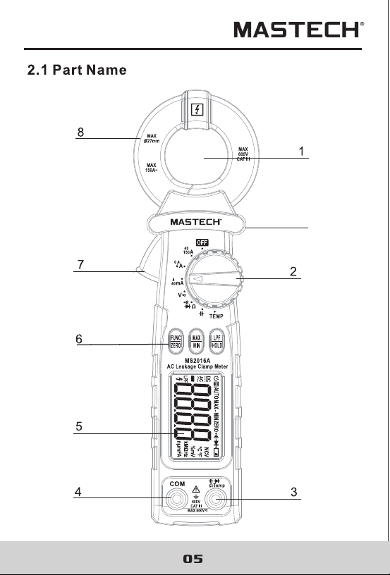
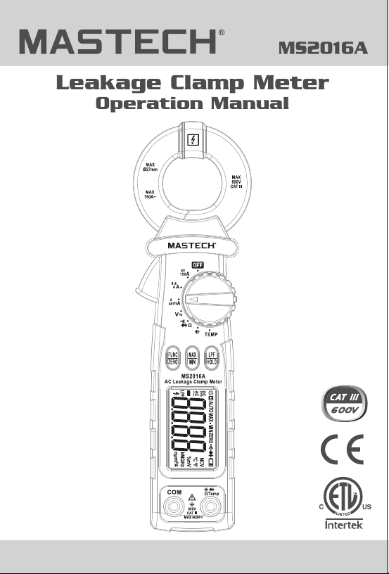
(1) The central of the clamp head
(2) Transfer switch
(3) Resistance, capacitance, voltage,diode and continuity
input jack
(4) Common end jack
(5) LCD display
(6) Function choice button
(7) Trigger
(8) Current clamp head: used for leakage current measurement.
(9) Protective barrier
HOLD/LPF button: used for reading hold and LPF(50Hz/
60Hz)function control.
FUNC/ZERO button: used for measuring function switch
and current clearing function control.
MAX/MIN button: used for maximum/minimum measure-
ment function switch and leakage current measeuring.
OFF position: used for shutting off the power.
INPUT jack: voltage, resistance, capacitance, diode,
circuit connection input wire connecting and temperature
terminal.
COM jack: voltage, resistance, capacitance, diode, circuit
connection common wire connecting and temperature
terminal.
Transfer switch: used for selecting function and
measuring range.
9
Automatic measuring range and manual measuring
range.
Full measuring range overload protection.
The maximum allowable voltage between
measurement end and ground: 600V DC or AC(RMS)
Operational height: maximum 2000m
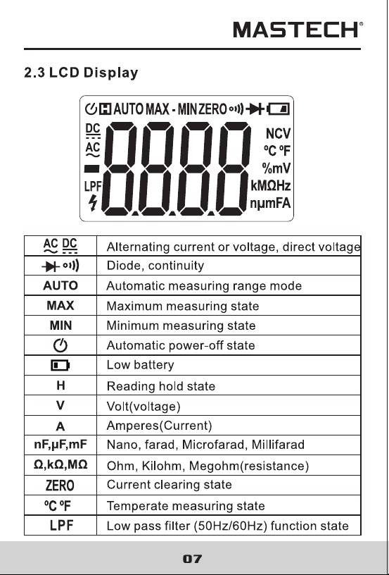
Display: LCD.
Displayed maximum value: 4000 counts.
Polarity indication; automatical indication, "-" means
negative polarity.
Exceeding measuring range display: " OL ".
Sampling rate: about 3 times/sec.
Unit display: has function and power unit display.
Auto off time: 30 min.
Power supply: 2x1.5V AAA Batteries.
Battery undervoltage indication: LCD displays" "
symbol.
Temperature coefficient: less than 0.1 x accuracy/℃.
Operational temperature: 18℃~28℃.
Storage temperature: -10℃~50℃.
Dimension: 213x62x38mm (8.4x2.44x1.5in).
Weight: about 238g(8.4oz)-include battery.
Indoor use.
-
-
-
-
-
-
-
-
-
-
-
-
-
-
-
-
-
-
-
Automatic measuring range and manual measuring
range.
Full measuring range overload protection.
The maximum allowable voltage between
measurement end and ground: 600V DC or AC(RMS)
Operational height: maximum 2000m
Display: LCD.
Displayed maximum value: 4000 counts.
Polarity indication; automatical indication, "-" means
negative polarity.
Exceeding measuring range display: " OL ".
Sampling rate: about 3 times/sec.
Unit display: has function and power unit display.
Auto off time: 30 min.
Power supply: 2x1.5V AAA Batteries.
Battery undervoltage indication: LCD displays" "
symbol.
Temperature coefficient: less than 0.1 x accuracy/℃.
Operational temperature: 18℃~28℃.
Storage temperature: -10℃~50℃.
Dimension: 213x62x38mm (8.4x2.44x1.5in).
Weight: about 238g(8.4oz)-include battery.
Indoor use.
-
-
-
-
-
-
-
-
-
-
-
-
-
-
-
-
-
-
-
1) Turn the transfer switch to turn on the power. When battery
voltage is low (about2.4V), LCD displays " " symbol,
replace the battery.
2) " " symbol means that input voltage or current should not
be more than the specified value, which is to protect the
internal line from damage.
3) Place transfer switch to required measuring function
and range.
4) When connecting line, first connect the common test line,
then connect charged test line. When removing line, remove
charged test line first.
Electric shock hazard. Remove the probe measuring with
current clamp.
1) Measuring switch is placed to position A. At this time, the
meter is in AC current measurement state. Choose appropri-
ate measuring range.
2) Hold the trigger, open clamp head, clip one lead of measure-
ment circuit to be tested in the clamp.
3) Read the current and frequency value on the LCD display.
1) Clamping two or more leads of circuit to be tested
simultaneously will not get the correct measuring results.
2) To get accurate reading, connect the lead to be tested at
the center of current clamp.
3) " " indicates that maximum input AC current is 150A.
4) Do not touch or hand hold position over protective barrier,
when measure current.
4) Do not touch or hand hold position over protective barrier,
when measure current.
MGL Global Solutions (China) Company Limited
72 Puxing East Road,Qingxi,Dongguan,
Guangdong,523649,China
Contact number:0769-81901647
E-mail: [email protected]

MGL Global Solutions (China) Company Limited
72 Puxing East Road,Qingxi,Dongguan,
Guangdong,523649,China
Contact number:0769-81901647
E-mail: [email protected]