Loading ...
Loading ...
Loading ...
assembly and alignment
ASSEMBLY AND ALIGNMENT
Assembling the Lower Blade Guard
NOTE: For compact shipment the lower blade guard
has been partially disconnected.
!. The slide compound miter saw has a spring loaded
pin to lock the miter saw in the !owered position. To
release push the handle down slightly, pull the lock-
ing knob and give a quarter turn,
2. Release pressure on the handle and allow the saw
to rise to its up position
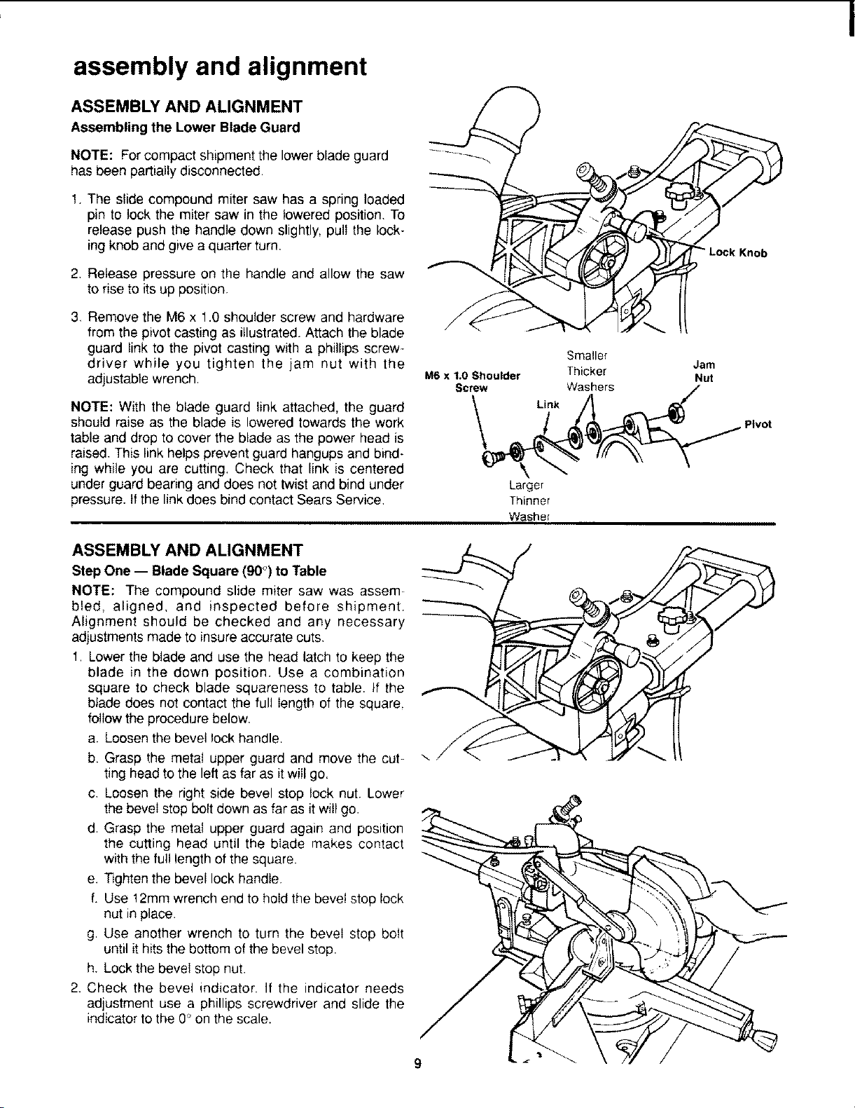
3, Remove the M6 x 1.0 shoulder screw and hardware
from the pivot casting as illustrated. Attach the blade
guard link to the pivot casting with a phillips screw-
driver while you tighten the jam nut with the
adjustable wrench,
NOTE: With the blade guard link attached, the guard
should raise as the blade is lowered towards the work
table and drop to cover the blade as the power head is
raised. This link helps prevent guard hangups and bind-
ing while you are cutting, Check that link is centered
under guard bearing and does not twist and bind under
pressure, tf the link does bind contact Sears Service,
Smaller
Jam
M6 x 1.0 Shoulder Thicker Nut
Screw Washers
Link
Pivot
Larger
Thinner
Washel
ASSEMBLY AND ALIGNMENT
Step One -- Blade Square (90°) to Table
NOTE: The compound slide miter saw was assem-
bled, aligned, and inspected before shipment.
Alignment should be checked and any necessary
adjustments made to insure accurate cuts.
1. Lower the blade and use the head latch to keep the
blade in the down position. Use a combination
square to check blade squareness to table. If the
blade does not contact the full length of the square.
follow the procedure below,
a. Loosen the bevel lock handle.
b. Grasp the metal upper guard and move the cut-
ting head to the left as far as it will go.
c. Loosen the right side bevel stop lock nut. Lower
the bevel stop bolt down as far as it will go.
d. Grasp the metal upper guard again and position
the cutting head until the blade makes contact
with the full length of the square.
e. Tighten the bevel lock handie
f. Use 12mm wrench end to hold the bevel stop lock
nut in place.
g Use another wrench to turn the bevel stop bolt
until it hits the bottom of the bevel stop.
h. Lock the bevel stop nut.
2. Check the bevel indicator, If the indicator needs
adjustment use a phillips screwdriver and slide the
indicator to the 0" on the scale.
9
Loading ...
Loading ...
Loading ...