Loading ...
Loading ...
Loading ...
7
ASSEMBLY
Riding Mower Preparation
1. Remove the upper crating material from the shipping pallet, and cut any
bands or tie straps securing the riding mower to the pallet.
2. If the deck is not in the highest mowing position (pulled all the way back),
use the deck lift handle to raise the deck to its highest position. Refer to the
Controls & Features section for instructions on raising and lowering the deck.
3. Disengage the parking brake.
4. Engage the transmission bypass rods on each side of the riding mower; then
carefully roll the riding mower off the shipping pallet. The transmission bypass
rods (one for each the RH and LH transmission) are located on the rear of the
riding mower, just inside each rear wheel. Engage the bypass rods by pulling
each one out and to the right then letting it return to lock it into place. See
Figure 1.
a
a
b
Figure 1
5. Disengage the bypass rods after rolling the riding mower off the pallet. See
Figure 1.
6. Remove the deck wash hose coupler from the manual bag and store for
future use.
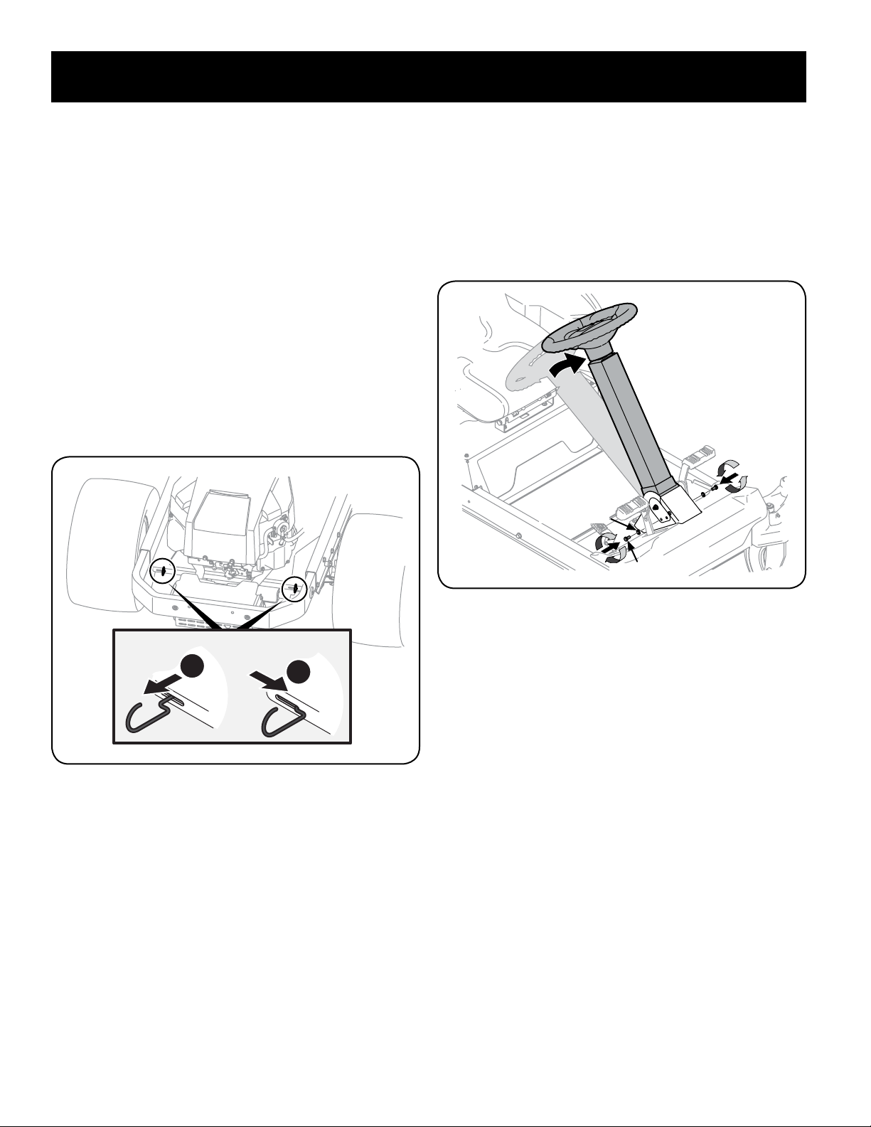
Steering Wheel Column
The steering wheel column is tilted all the way back for shipping. Place the steering
column in one of the two positions and secure in place with the hex screws and flat
washers packed separately. See Figure 2.
Hex Screw
Flat Washer
Figure 2
Steering Wheel
1. Remove the hardware for attaching the steering wheel from beneath the
steering wheel cap. Carefully pry off the steering wheel cover to remove the
hardware.
2. With the wheels of the riding mower pointing straight forward, place the
steering wheel over the steering shaft.
Contents of Crate
• One Zero-Turn Riding Mower • One Deck Wash Hose Coupler • One Operator’s Manual
• One Engine Operator’s Manual • Two Hex Screws and Flat Washers
Loading ...
Loading ...
Loading ...