Loading ...
Loading ...
Loading ...
DRYER GAS SUPPLY REQUIREMENTS
Type of Gas
This dryer is equipped for use with natural gas. It is design-certified
by CSA International for LP (propane and butane) gases with
appropriate conversion. No attempt shall be made to convert dryer
from gas specified on serial/rating plate for use with a different gas
without consulting the serving gas supplier. Conversion must be
done by a qualified service technician.
Gas conversion kit part numbers are listed on gas valve burner
base.
Gas Supply Line
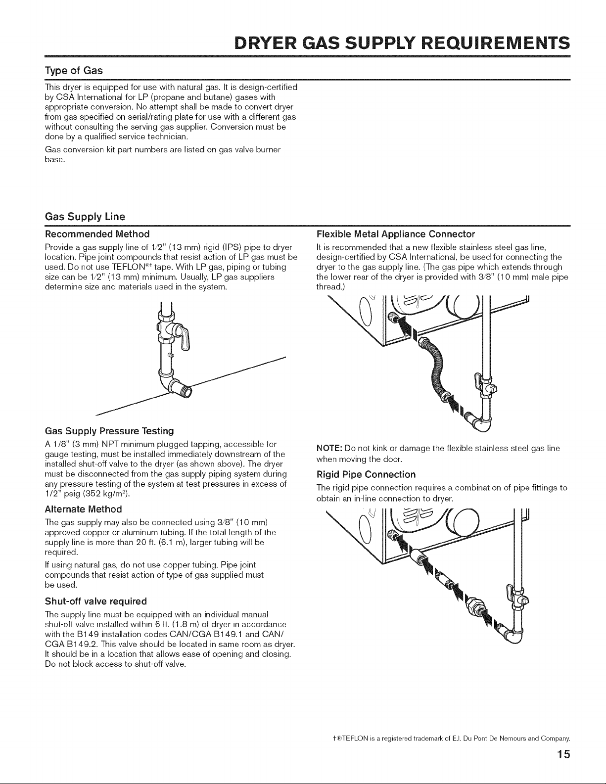
Recommended Method
Provide a gas supply line of 1/2" (1 3 mm) rigid (IPS) pipe to dryer
location. Pipe joint compounds that resist action of LP gas must be
used. Do not use TEFLON Rt tape. With LP gas, piping or tubing
size can be 1/2" (1 3 mm) minimum. Usually, LP gas suppliers
determine size and materials used in the system.
Flexible Metal Appliance Connector
It is recommended that a new flexible stainless steel gas line,
design-certified by CSA International, be used for connecting the
dryer to the gas supply line. (The gas pipe which extends through
the lower rear of the dryer is provided with 3/8" (10 mm) male pipe
thread.)
Gas Supply Pressure Testing
A 1/8" (3 mm) NPT minimum plugged tapping, accessible for
gauge testing, must be installed immediately downstream of the
installed shut-off valve to the dryer (as shown above). The dryer
must be disconnected from the gas supply piping system during
any pressure testing of the system at test pressures in excess of
1/2" psig (352 kg/m2).
AIternate Method
The gas supply may also be connected using 3/8" (10 mm)
approved copper or aluminum tubing. If the total length of the
supply line is more than 20 ft. (6.1 m), larger tubing will be
required.
If using natural gas, do not use copper tubing. Pipe joint
compounds that resist action of type of gas supplied must
be used.
Shut-off valve required
The supply line must be equipped with an individual manual
shut-off valve installed within 6 ft. (1.8 m) of dryer in accordance
with the B149 installation codes CAN/CGA B149.1 and CAN/
CGA B149.2. This valve should be located in same room as dryer.
It should be in a location that allows ease of opening and closing.
Do not block access to shut-off valve.
NOTE: Do not kink or damage the flexible stainless steel gas line
when moving the door.
Rigid Pipe Connection
The rigid pipe connection requires a combination of pipe fittings to
obtain an in-line connection to dryer.
t-_TEFLON is a registeredtrademarkof E.I.Du Pont De Nemoursand Company.
15
Loading ...
Loading ...
Loading ...