Loading ...
Loading ...
Loading ...
Rinnai Australia 30 Installation Manual
GENERAL INSTALLATION INSTRUCTIONS
SERVICE CONNECTION POINTS
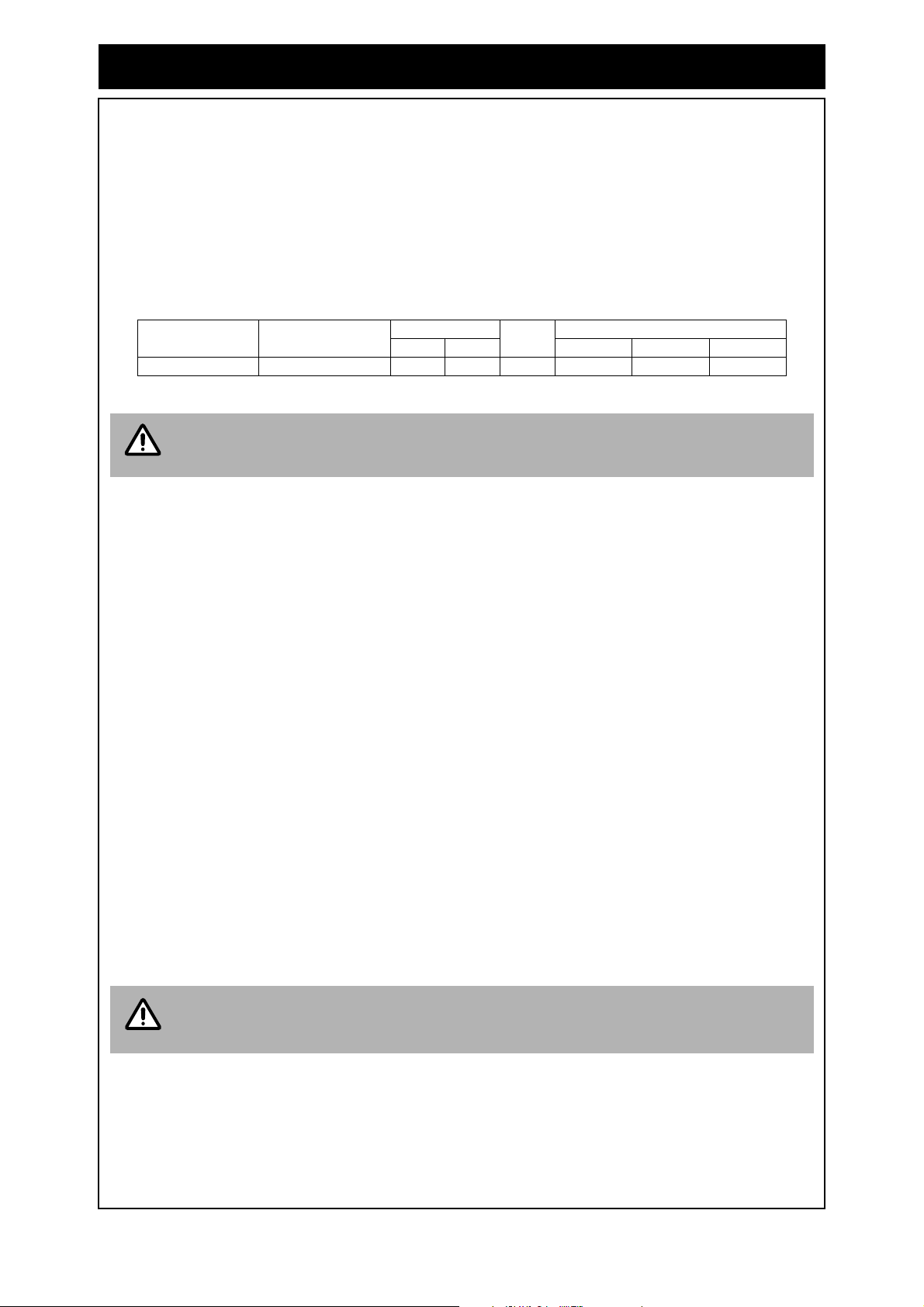
See Table 1 for appliance connection / fitting dimensions.
An Approved full flow isolation valve and disconnection union MUST be fitted to the cold water inlet.
A non return valve is not required unless required by local regulations.
Isolation Valves must not be fitted directly to the appliance.
If may be necessary to fit a temperature limiting device for delivery to areas used primarily for the
purposes of personal hygiene. Refer to the ‘Water Heater and Controllers Installation Configurations’
Section of this document.
Purge gas and cold water supply lines to remove air and swarf before final connection of the
appliance. Swarf in either the gas or water supplies may cause damage.
Table 1.
RINNAI WIRELESS WATER CONTROLLERS
A wireless water controller installation utilises a 'transceiver' and up to 4 wireless water controllers.
Unlike most remote control systems, there is 'two way' communication between the transceiver and
controllers. The 'transceiver' is connected by electrical cable to the water heater. The 'transceiver'
transmits control signals received from the wireless controllers operated by the user to the water
heater. The 'transceiver' transmits operational 'status' signals from the water heater which are
received by individual wireless controllers to ensure controller displays reflect the operational status
of the water heater.
Wireless water controllers can be installed in conjunction with Universal and Deluxe wired water
controllers and will function as described in the Operation Section of this manual. Refer to page 10 to
confirm the maximum number and combination of water controllers that can be fitted.
Master and Sub controllers and temperatures
Only one wireless or wired controller can be designated the 'Master Controller' (MC). This controller
is normally used in the kitchen and usually has a maximum temperature of 55°C, is sufficient for
almost all kitchen applications. Temperatures higher than 55°C are possible but usually unnecessary
and will result in higher gas use and increase the risk of burns. Some conditions regarding Master
Controller maximum temperatures are as follows:
• Temperatures of 55°C or higher can only be selected on the controller designated as Master
Controller (MC) if the transceiver 'Max Temp' is also programmed to 55°C or higher.
• The temperature of hot water delivered is always limited to the maximum temperature programmed
into the water heater itself. For example, if the transceiver maximum temperature is programmed to
55°C and the water heater is limited to 50°C, the maximum temperature that the water heater will
deliver is 50°C. In this case 55°C will be displayed on the wireless Master Controller until a tap is
opened after which the display will revert to 50°C.
The remaining controllers are designated 'sub' controllers and are for use in bathrooms, toilets and
laundries. The temperature limit for all 'Sub' controllers is always 50°C to minimise the risk of burns in
these areas.
Adhesive labels are included for individual identification of wireless controllers as master (Kitchen) or
sub (Bathroom No.) controllers. These labels are usually placed on the top back of the wireless water
controller body.
Model:
Gas Consumption
MJ/h
Water Supply kPa
Weight
kg
Fittings
Min. Max. Hot Cold Gas
REU-VRM2626WD 199 200 1000 16 R ¾ (20mm) R ¾ (20mm) R ¾ (20mm)
Note that these dimensions are NOT an indication of the pipe sizes required.
The water heater maximum temperature cannot be adjusted by the user.
These adjustments can only be carried out by a qualified and licensed tradesperson.
NOTE
IMPORTANT
Loading ...
Loading ...
Loading ...