Loading ...
Loading ...
Loading ...
1110
CULTIVATOR EDGER PRUNING SAW HEDGE TRIMMER BRUSHCUTTER
the cords should stick out 15 cm each side,
8. Pull the cords to free them from the notches, refit the spool
cover.
Never use cutting device other than those supplied by the
manufacturer.
(Steel cord is never allowed).
Always use original spare parts in order to benefit from
continuous warranty.
Attaching The Tools To The Drive Shaft Assembly
• Rest the power unit/shaft assembly on a flat firm surface.
• Ensure that the clamping wing nut (2) is loose, pull out locator
pin (1).
• Carefully fit attachment drive shaft assembly (5) into coupler (3).
• After the attachment drive shaft is in the coupler, release the
locator pin (1).
• Turn the attachment drive shaft until the locator pin engages
with the locating hole (4) in the drive shaft, when this has
happened it will not be possible to twist the drive shaft.
• Secure the drive shaft by tightening the clamping wing nut (2).
Transportation
• Never transport the multi-tool with the engine running. An
engine that’s running could be accidently accelerated causing
the attachment to operate.
• When carrying by hand, the engine should be pointing forward.
Starting and Stopping the Engine
Starting the Engine
CAUTION
Do not pull the starter cord all the way out and do not let go of the
starter handle when the cord is extended, this can damage the
starter mechanism.
Before starting the engine, inspect the entire unit for loose fittings or
fuel leaks, and verify that the cutting attachment is properly installed
and securely fastened.
Place the unit on a flat, firm place. Keep
the cutting head clear of any obstructions.
1. Check that there is fuel in the tank
and that the fuel cap is screwed on
tightly.
(1) Cap
(2) Fuel tank
2. When starting a cold
engine move the choke
lever (behind the air cleaner
cover) to the closed
position.
(1) Choke lever
(2) Closed
(3) Open
3. If the engine has been running and is still warm, move the
choke lever to the open position.
4. Press the priming bulb under the carburettor repeatedly until
excess fuel can be seen returning to the tank through the clear
fuel return pipe.
5. Slide the ignition switch (2) on the trigger grip away from the
STOP position (See Diagram .C on the next column).
6. To set the throttle in the start position.
- Depress the safety lever (4)
- Squeeze the throttle lever (1) fully.Hold down the starting
button (3) while releasing the throttle lever.
- The throttle lever will be held partly open until it is squeezed
again.
(1) Throttle lever
(2) Ignition Switch
(3) Starting button.
(4) Safety Lever
BC 230B S2, BC 260 S2 and
BC 260B S2
BC 325 S2
Diagram .C
7. While holding the unit firmly, pull out the
starter rope quickly.
8. After the engine has started, open the
choke gradually.
9. Allow the engine to run for 2 to 3 minutes
to warm up before starting work.
NOTE
Overchoking
• Should the engine become flooded due to over-choking set the
ignition switch to the STOP (O) position Fig 35, unscrew the
spark plug, wipe it dry or replace, pull the recoil starter several
times without the spark plug in place and with the choke in the
open position. This will help clean and ventilate the combustion
chamber.
STOPPING THE ENGINE
• Set the engine to idling by releasing the throttle lever.
• Set the ignition switch to the STOP (O) position.
• If the engine fails to stop, set the choke lever to the closed
position to stall the engine; do not use the machine until the
ignition switch is repaired.
RUNNING IN
• During the first ten hours of work, avoid running the engine
at maximum speed for a prolonged period until all the
components have bedded in. After the engine has been run-in,
it will reach its maximum power.
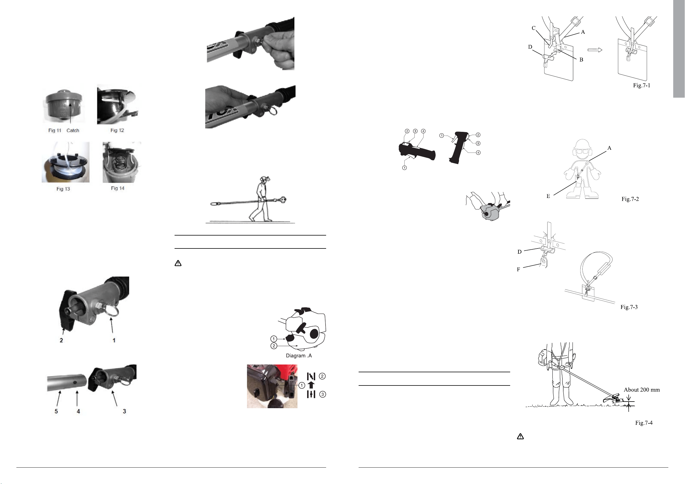
Wearing the Harness
The harness has a quick-release mechanism that allows
you to immediately release the machine from the harness
in an emergency.
Attaching the side hook
NOTE
If side hook (D) has disengaged from hook (B), engage it.
1. Insert hook (B) into side hook (D).
2. While holding hook (B) and side hook (D) in place,
insert stopper (C) into the hole on hook (B).
Adjusting the harness
1. As shown in the diagram, adjust the harness (A) so that
hip pad (E) is against your right hip. (Fig.7-2)
2. Before starting to work, attach the side hook (D) to the
suspension point (F) on the shaft tube. (Fig.7-3)
Recommended working position
CAUTION
If releasing both hands from the handle, use extreme care. Suddenly
Diagram .B
Loading ...
Loading ...
Loading ...