Loading ...
Loading ...
Loading ...
Part number 550-100-260/0520
63
ECO
®
Tec
GAS-FIRED WATER BOILER – 80/110/150/199 BOILER MANUAL
AUTOMATIC
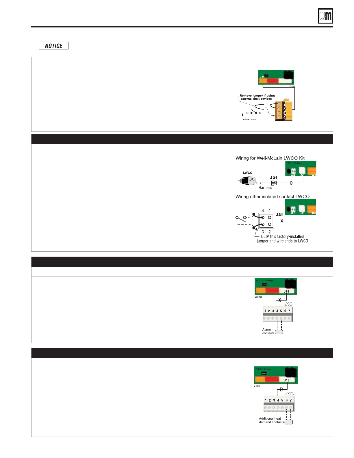
1. Remove factory-installed jumper and connect isolated contacts of external
limits across J20 pins 3 and 4 to cause the control to shut down the boiler on
limit opening, then automatically restart 150 seconds after the limit closes.
2. See drawing at right and wiring diagram (
Figure 70, page 66
).
See
Figure 70, page 66
for details.
G. Low water cutoff (LWCO) – Required (Installer Supplied)
1. Install a low water cut-off (required) (see Figure 51, page 41).
2. Wiring Weil-McLain LWCO Kit:
a. When possible, use the Weil-McLain Low water cut-off kit listed in the back
of this manual. It includes a probe-type low water cut-off and provides a
simple harness connection for the wiring.
b. Connect as shown at bottom center in the control wiring diagram
(
Figure 70, page 66
)
.
3. Wiring another LWCO — must have isolated contact:
a. Other low water cut-offs can be used with the ECO
Tec only if the device
uses an isolated contact for the LWCO function.
b. Connect as shown at bottom right.
See
Figure 70, page 66
for details.
H. Alarm contacts – OPTIONAL
1. The control’s alarm dry contact (J18, terminals 4 and 5) closes when the
boiler enters manual lockout only.
2. Connect these terminals for remote alarm notification.
3. Contact electrical ratings: 24VAC or less; 0.5 amp or less.
See Figure 70, page 66 for details.
I. Additional heat demand contacts – OPTIONAL
1. The circuit board can be set to activate another heat source using its additional
heat demand dry contacts through terminal block J18 pins 6 & 7.
2. Connect these terminals to call for heat from the other heat source.
3. Contact electrical ratings: 24VAC or less; 0.5 amp or less.
4. Set the control to activate the heat demand contacts as needed.
5. For Additional Heat Demand , refer to setup in Control section for more
information.
See Figure 70, page 66 for details.
Field wiring (see wiring diagram, Figure 70, page 66) (continued)
Combi models use Input/Output pairs 1 and 4 for 3-way valve operation and cannot be used for any
other purpose. Use Input 2 for Indirect DHW (if needed) and Input 3 for Space Heating applications.
Loading ...
Loading ...
Loading ...