Loading ...
Loading ...
Loading ...
ECO
Tec 80/110/150 Zone valve zoning direct
connection (internal boiler circulator provides
flow for system
)
Part number 550-100-260/0520
49
ECO
®
Tec
GAS-FIRED WATER BOILER – 80/110/150/199 BOILER MANUAL
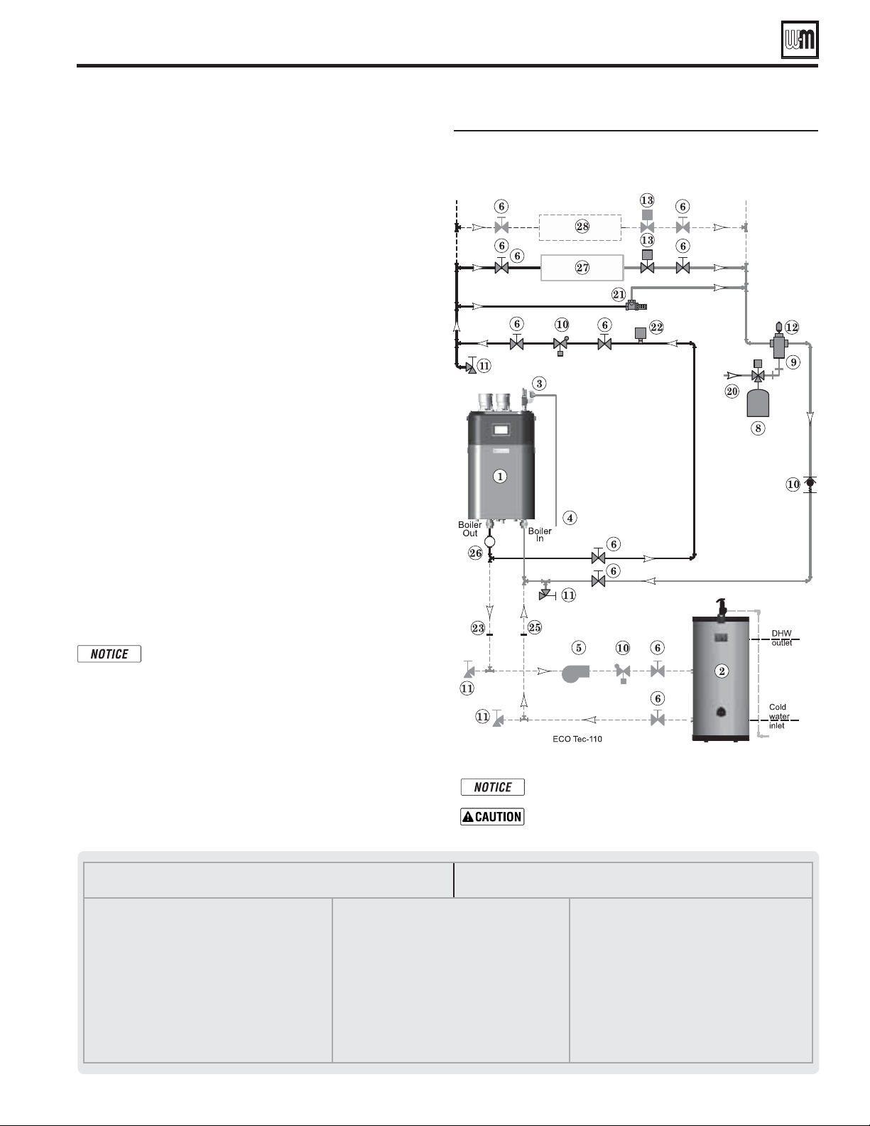
ZONE VALVE zoning – direct connection
(Shown with optional DHW piping)
See Figure59.
1. This configuration is for zone valve systems that qualify to
use direct connection piping based on the criteria on page 46
only. If system does not qualify, pipe using primary/secondary
piping. See pages 51-55 for piping suggestions and guidelines.
2. Systems zoned with zone valves MUST use a by-pass pressure
regulator (Taco 3196 or equivalent – Item 21) unless using
modulating type of circulator that has protection against
dead heading.
Expansion Tank required
1. Provide a system expansion tank following the guidelines on
page 46 or page 48.
2. DO NOT use a closed-type tank if connecting to a water
heater that is equipped with an automatic vent.
Domestic Hot Water (DHW) tank, if used
1.
DHW direct connection—Pipe from the near-boiler piping
to the DHW tank’s boiler connections as shown.
2. DHW as zone— A DHW tank can be connected as a zone
if a DHW tank is NOT already connected to the boiler. See
notices on page 149 to ensure compliance with the 2007
Energy Act. See Control section in this manual, page 84 to
change TARGET MODULATION SENSOR to System Supply
when system sensors are installed.
3. DHW Priority operation— Using Priority 1 for DHW
(default) will turn off lower priorities during DHW calls. The
MAX ON TIME setting can be adjusted to limit how long
this occurs. Use Priority 2 or 3 for DHW if DHW priority
is not desired.
Overriding the Outdoor Reset function by setting
control to DHW mode when system is intended
for space heating may violate Section 303 of the
2007 Energy Act. See page 149 for compliance
information and exemptions.
Controlling the circulators (Direct Connect only)
1. In a direct connect set-up, by default the internal circulator
will turn on for any configured heating call or DHW call.
2. If an Indirect tank is used, as in Figure 59, a secondary
circulator will have to be configured to turn on when the
indirect tank input is active.
Connect zone valve end switches to Priority 2 input.
Use isolation relays if connecting 3-wire zone valve end
switches to the input.
.
This is a common legend for all piping diagrams.
Not all Items listed appear in every figure.
1 ECO
Tec boiler
2 Indirect Water Heater, if used
3 Relief valve, supplied with boiler, field piped — MUST
be piped to Boiler In connection — see page 13 for
information
4 Relief valve piping to drain — see page 48
5 DHW circulator
6 Isolation valves
7 System circulator
8 Expansion tank, diaphragm type, if used
9 Air separator
10 Spring check valves
11 Purge/drain valves
(one drain valve shipped loose with boiler)
12 Auto air vent
13 Zone valves
14 Primary/secondary connection (tees no more than 12
inches apart)
15 Expansion tank, closed type, if used (some chiller
systems may use a diaphragm-type expansion tank)
16 Water chiller
17 Check valve
18 Y-strainer
19 Balancing valve
20 Make-up water supply – Use applicable codes to
determine if backflow preventers, pressure reducing
valves, and fill valves may be required
21 By-pass pressure regulator, REQUIRED for zone valve
systems unless other provision is made
22 High limit temperature control
23 DHW tank boiler water supply connection, when used
24 Zone circulator
25 DHW tank boiler water return connection, when used
26 Pressure/temperature gauge, supplied with boiler, field
piped
27 Heating circuits
28 Additional heating circuits, if any
Direct Connect System Piping - Single Boiler System (continued)
80/110/150 Boilers only
Loading ...
Loading ...
Loading ...