Loading ...
Loading ...
Loading ...
Throttle and Offset Regulating screw (ONLY for
use by a qualified technician, using calibrated
combustion test instruments)
Part number 550-100-260/0520
102
ECO
®
Tec
GAS-FIRED WATER BOILER – 80/110/150/199 BOILER MANUAL
Startup — fi nal checks (continued)
If combustion at either high or
low fi re is outside the range given
in Figure 95, page 105 , follow the
procedure given on this page or
page 105 for adjusting the gas valve.
If adjustment does not correct
the problem, then shut down the
boiler and contact your local Weil-
McLain representative. The gas valve
adjustment must be done only by a
qualifi ed technician, using calibrated
test instruments. Failure to comply
could result in severe personal injury,
death or substantial property damage.
7. Measure natural gas input:
a. Operate boiler 10 minutes. Turn off other appliances.
b. At natural gas meter, measure time (in seconds)
required to use one cubic foot of gas.
c. Calculate gas input:
3600 x 1000
= Btuh
number of seconds from step b
d. Btuh calculated should approximate input rating on
boiler rating label.
8. Use the control display to navigate to Manual test mode
(see Figure 89, page 95 ) and force the fi ring rate to LOW
(low fi re).
9. Look at the flame through the flame inspection
window. The low fi re fl ame should be stable and evenly
distributed over burner surface with a uniform orange
color.
10. Repeat the combustion test as instructed in the previous
steps.
11. Use the control display to navigate to Manual test mode
(see Figure 89, page 95 ) and force the fi ring rate to AUTO
(normal operation).
12. Reinstall the vent fl ue cap and ensure its sealed.
You must reinstall the vent fl ue cap to prevent
fl ue gas spillage into the boiler enclosure.
Failure to comply could result in severe
personal injury, death or substantial property
damage.
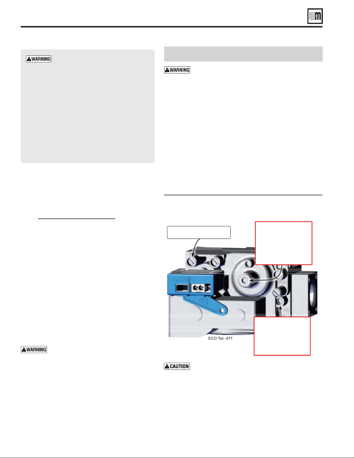
Gas Valve Adjustment
attempt to adjust the throttle or offset screw
unless done by a qualified technician, and with the
use of calibrated combustion test instruments. Adjust
the throttle or offset screw only as needed to meet
the combustion values given in Figure 94, page 103 .
Must confi rm correct low fi re RPM before making any
adjustments to Offset regulating screw.
1. Throttle screw adjustment is if specified
elsewhere in this manual or if combustion tests indicate the
need, as explained under “
,” page 100 .
2. Boiler behavior that might indicate a need to check combustion
values at high fi re (as per page 100 ) to verify boiler is in adjustment
include: difficulty igniting, poor flame stability at low fire,
combustion noise or high carbon monoxide values.
3. Combustion readings must be taken at both high fi re and low fi re.
DO NOT attempt an adjustment of the throttle screw at low fi re.
See Figure 93 for location of the throttle screw.
Adjust the throttle adjustment screw in small movements.
Make sure that the MAX RATE and MIN RATE for the PRIORITY that
you are planning on testing on are set to 100% and 10% respectively.
Then navigate to the MANUAL TEST MODE menu from the
DIAGNOSTICS menu ( Figure 89, page 95 ). After forcing the boiler to
HIGH FIRE insure the BLOWER SPEED has achieved the RPM listed on
Figures 98 or 99 ( Pages 110 or 111 ). Take CO
2
and CO readings and
adjust gas valve accordingly to Figures 93 and 94 allowing adequate time
for the combustion analyzer to stabilize.
Turn clockwise
to increase CO
2
. 3
Turn counter-clockwise to
decrease CO
2
. 4
Note: Must remove cover.
Throttle adjustment screw
Turn counter-clockwise
to increase CO
2
. 4
Turn clockwise to
decrease CO
2
. 3
Loading ...
Loading ...
Loading ...