Loading ...
Loading ...
Loading ...
Part number 550-100-260/0520
62
ECO
®
Tec
GAS-FIRED WATER BOILER – 80/110/150/199 BOILER MANUAL
Field wiring (see wiring diagram, Figure 70, page 66) (continued)
Combi models use Input/Output pairs 1 and 4 for 3-way valve operation and cannot be used for any other
purpose. Use Input 2 for Indirect DHW (if needed) and Input 3 for Space Heating applications.
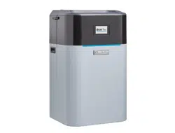
D. System supply and return temperature sensors – Recommended when using
primary secondary piping design. Connector J19
1. It is recommended to use two (2) strap-on temperature sensors (separate kit
option). Attach one to the system supply piping and the other to the system
return piping. For piping larger than 5 inch diameter or nonmetallic piping,
using immersion sensors will provide faster response.
2. Locate the supply sensor at least six pipe diameters, but no further than 3
feet, downstream from the boiler connection to the main to ensure adequate
mixing.
3. Return sensor – wire between J19 #1 and #2.
4. Supply sensor – wire between J19 #3 and #4.
5. Thermostat wire can be used to connect these sensors.
6. The Control compares the system return temperature with the system supply
temperature.
It is recommended for all primary/secondary heating systems
shown in this manual that the System Supply and Return sensors
to be installed for proper control function. System may not
properly provide desired temperature if sensors are not installed
according to these instructions.
Strap to supply & return piping
See
Figure 70, page 66
for details
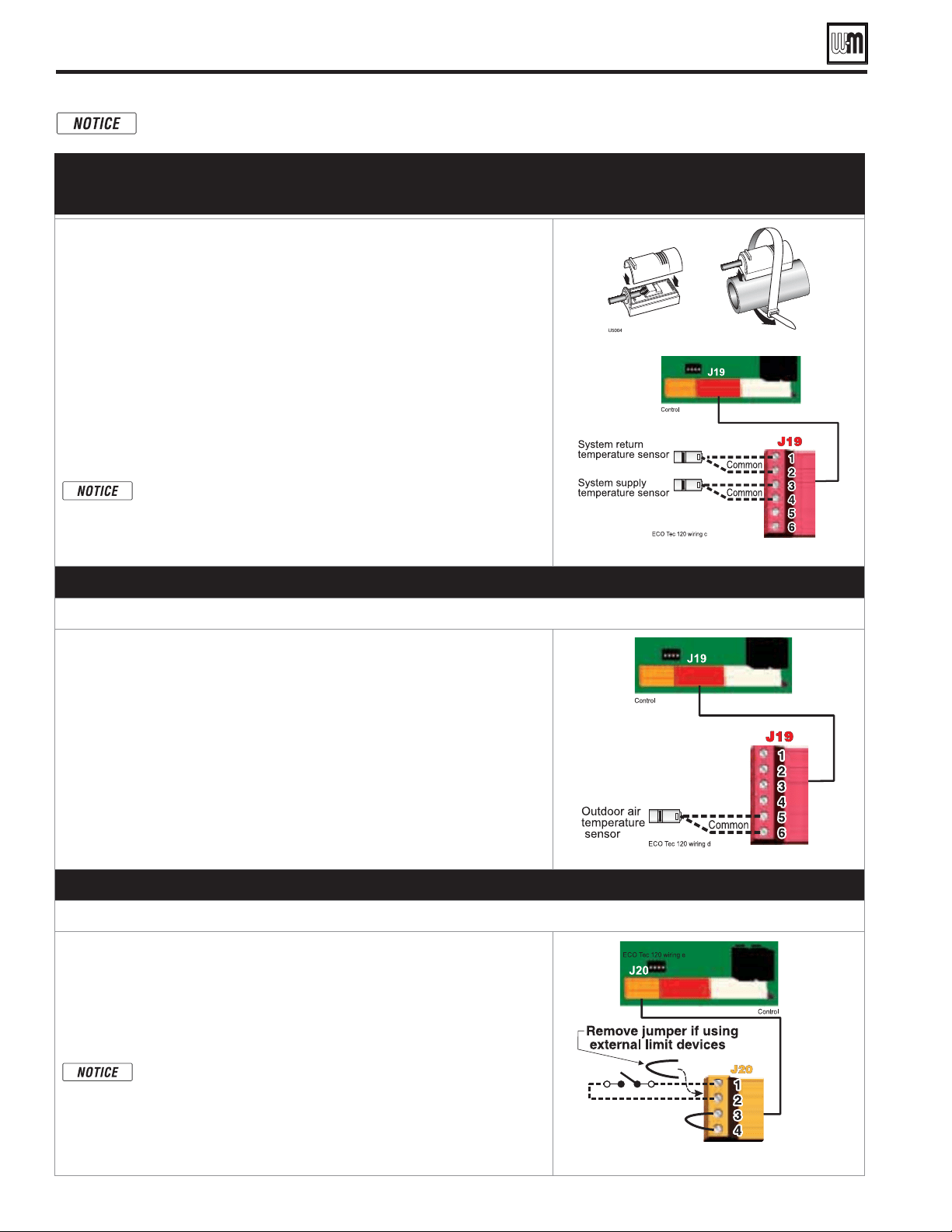
E. Outdoor temperature sensor – REQUIRED unless exempted
Connector J19
1. The control provides programmable options if using an outdoor
temperature sensor. This sensor is supplied with the boiler.
2. The outdoor sensor must be installed unless specifically
exempted in the Energy Act statement on page 149.
3. Mount the outdoor sensor on an exterior wall, shielded from direct sunlight
or flow of heat or cooling from other sources.
4. The wire outlet on the sensor must be oriented DOWN to prevent water
entry.
5. Connect the sensor leads to the terminal shown at right and in the wiring
diagrams (see
Figure 70, page 66
). Thermostat wire can be used to connect
the sensor.
See
Figure 70, page 66
for details
F. External limits – OPTIONAL
To cause MANUAL reset: Connector J20 #1 & #2
The control will require manual reset after circuit is interrupted
.
1. Remove factory-installed jumper and connect isolated contacts of external
limits across J20 pins 1 and 2 to cause the control to enter manual reset
lockout if the limit circuit opens. The limit must close and the control must
be manually reset using the procedure given in this manual. See drawing
at right and wiring diagram
Figure 70, page 66
.
The control will lockout when a limit in its manual reset circuit
opens (J20 pins 1 & 2). The control activates its alarm terminals
and shuts the boiler down. An operator (user or technician) must
manually reset the control to restart the boiler.
See
Figure 70, page 66
for details.
Loading ...
Loading ...
Loading ...