Loading ...
Loading ...
Loading ...
Part number 550-100-260/0520
61
ECO
®
Tec
GAS-FIRED WATER BOILER – 80/110/150/199 BOILER MANUAL
– As needed for systems
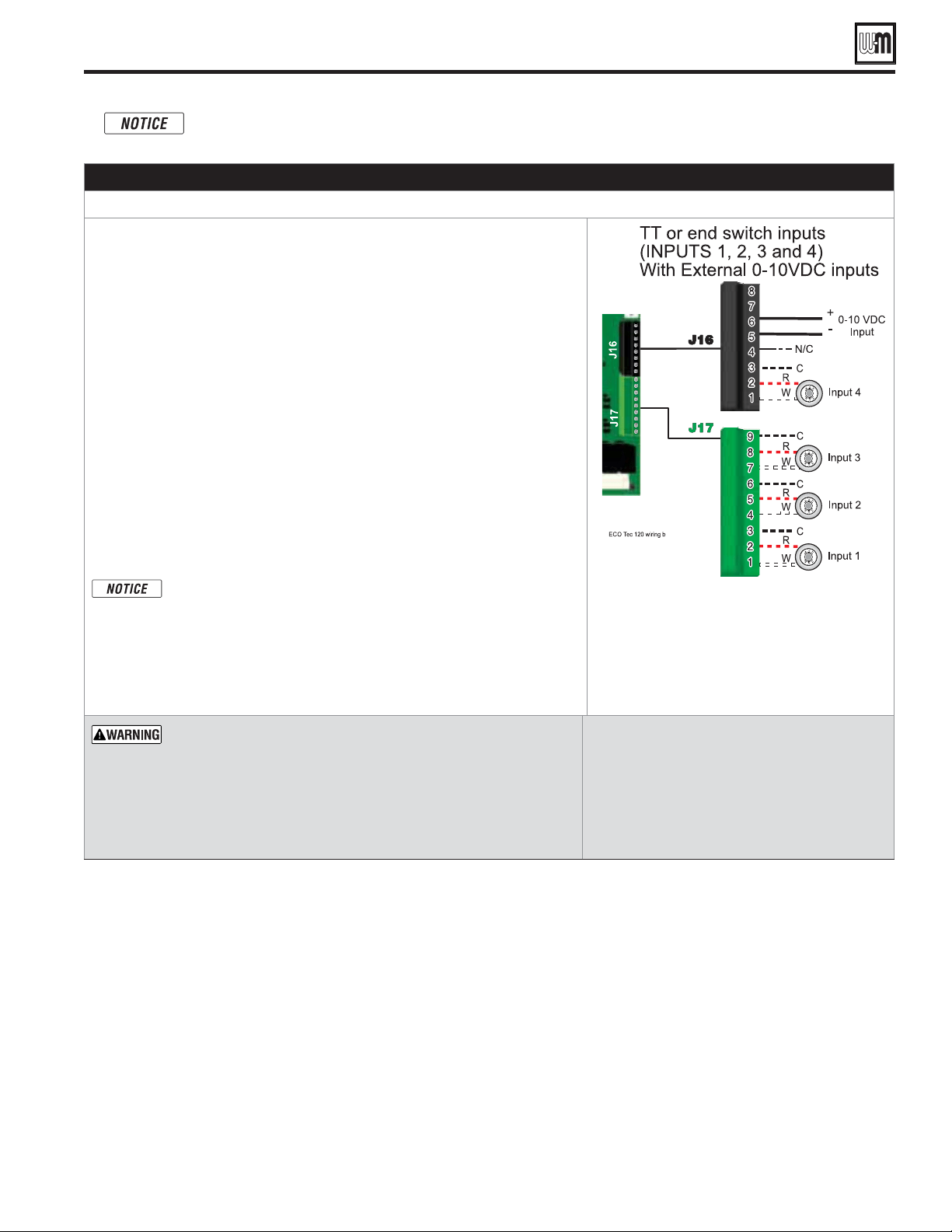
1. Input 1 – Connector J17 – 1, 2 & 3 (common)
2. Input 2 – Connector J17 – 4, 5 & 6 (common)
3. Input 3 – Connector J17 – 7, 8 & 9 (common)
4. Input 4 – Connector J16 – 1, 2 & 3 (common)
5. These four (4) inputs on each boiler can indicate a call for heat to the
control by means of a dry contact closure (thermostat, aqua
stat, or switch).
(See right and Figure 70, page 66).
6. The control provides inputs for up to four demands and up to three systems
(priorities).
7.
:
The DHW aquastat can be connected to any one of the four (4) input/output pairs
for Heating Only models and Inputs 2 or 3 for Combi models. The selected input
should be assigned to PRIORITY 1 during the WIZARD setup or manually in the
System Settings menu for Heating Only models or Priority 2 for Combi models
8. The default control setting uses each input (INPUT 1, INPUT 2, INPUT 3 and
INPUT 4) to control its respective 120VAC output (OUTPUT 1, OUTPUT 2,
OUTPUT 3 and OUTPUT 4). For Combi models, input 1 and 4 and output
1 and 4 are reserved for Combi calls for heat and 3-way valve operation.
Use of 0–10VDC input for modulation disables Input 2 T/T input
from creating calls for heat. See page 65 for instructions.
An input can be assigned to an AUX PUMP/OUTPUT function to
operate a system pump or interlock with a combustion air damper.
Inputs assigned for this function cannot be used for heat demand
operation. See page 91 and page 93 for more information on the
setup and selection of operating conditions.
See
Figure 70, page 66
for details.
— supply 24-volt power to the thermostat
circuits (Input 1, Input 2, Input 3 and Input 4 in Figure 70, page 66)
or attempt to supply 24 volts for any other application.
For thermostats that require a continuous 24-volt power source,
connect the common wire (“C”)
(see
Figure 70, page 66
)
.
Do NOT
exceed total amp draw per thermostat.
— If using 3-wire zone valves, use
relays to provide dry contacts to the Control
thermostat connections. The zone valve end
switches of 3-wire valves carry 24VAC from the
valve.
— 0.1 amps.
Field wiring (see wiring diagram, Figure 70, page 66) (continued)
Combi models use Input/Output pairs 1 and 4 for 3-way valve operation and cannot be used for any
other purpose. Use Input 2 for Indirect DHW (if needed) and Input 3 for Space Heating applications.
Loading ...
Loading ...
Loading ...