Loading ...
Loading ...
Loading ...
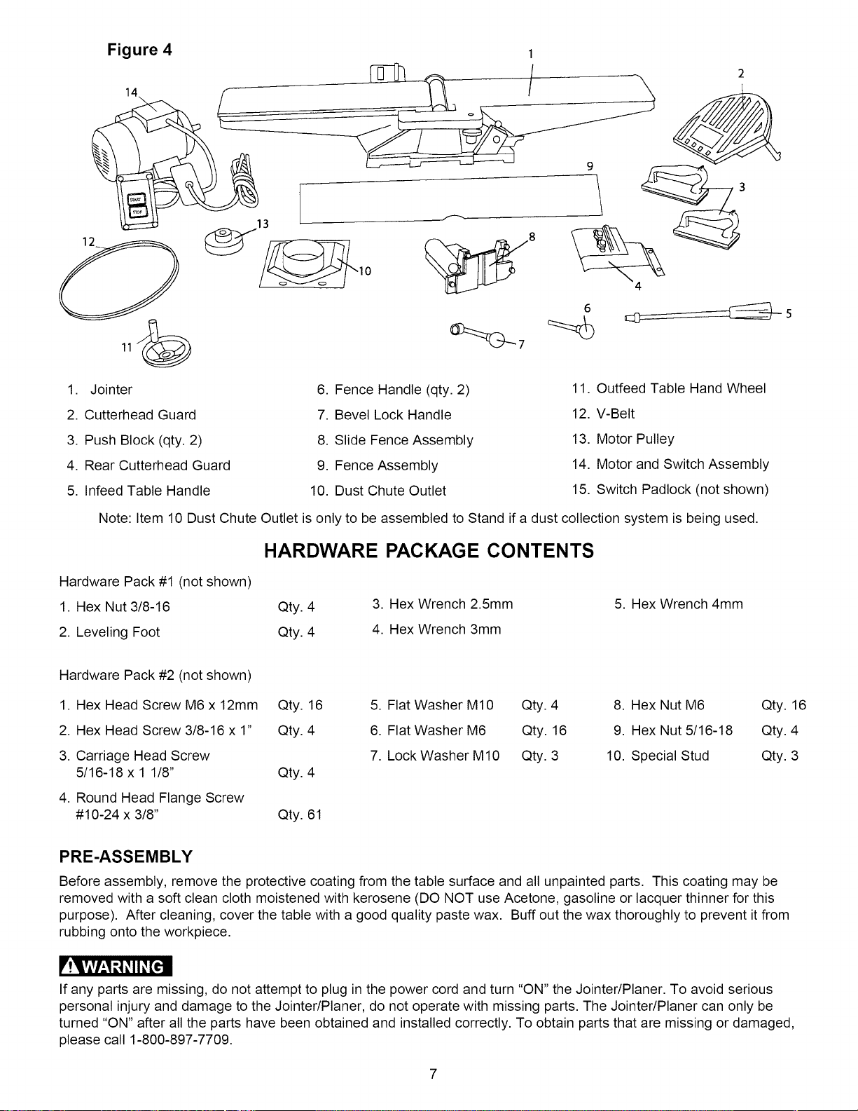
Figure 4 1
6
1. Jointer
2. Cutterhead Guard
6. Fence Handle (qty. 2)
7. Bevel Lock Handle
11. Outfeed Table Hand Wheel
12. V-Belt
3. Push Block (qty. 2)
4. Rear Cutterhead Guard
5. Infeed Table Handle
8. Slide Fence Assembly
9. Fence Assembly
10. Dust Chute Outlet
13. Motor Pulley
14. Motor and Switch Assembly
15. Switch Padlock (not shown)
Note: Item 10 Dust Chute Outlet is only to be assembled to Stand if a dust collection system is being used.
HARDWARE PACKAGE CONTENTS
Hardware Pack #1 (not shown)
1. Hex Nut 3/8-16 Qty. 4
2. Leveling Foot Qty. 4
3. Hex Wrench 2.5mm
4. Hex Wrench 3mm
5. Hex Wrench 4mm
Hardware Pack #2 (not shown)
1. Hex Head Screw M6 x 12mm Qty. 16
2. Hex Head Screw 3/8-16 x 1" Qty. 4
3. Carriage Head Screw
5/16-18 x 1 1/8" Qty. 4
4. Round Head Flange Screw
#10-24 x 3/8" Qty. 61
5. Flat Washer M10 Qty. 4
6. Flat Washer M6 Qty. 16
7. Lock Washer M10 Qty. 3
8. Hex Nut M6 Qty. 16
9. Hex Nut 5/16-18 Qty. 4
10. Special Stud Qty. 3
PRE-ASSEMBLY
Before assembly, remove the protective coating from the table surface and all unpainted parts. This coating may be
removed with a soft clean cloth moistened with kerosene (DO NOT use Acetone, gasoline or lacquer thinner for this
purpose). After cleaning, cover the table with a good quality paste wax. Buff out the wax thoroughly to prevent it from
rubbing onto the workpiece.
r'!q?ivhl _1_II_[€'ll
If any parts are missing, do not attempt to plug in the power cord and turn "ON" the Jointer/Planer. To avoid serious
personal injury and damage to the Jointer/Planer, do not operate with missing parts. The Jointer/Planer can only be
turned "ON" after all the parts have been obtained and installed correctly. To obtain parts that are missing or damaged,
please call 1-800-897-7709.
7
Loading ...
Loading ...
Loading ...