Loading ...
Loading ...
Loading ...
, Slide the slide trunnion bracket down into the
dovetail (F) of the slide fence assembly (G).
See Figure 14.
Slide Fence Assembly
Figure 14
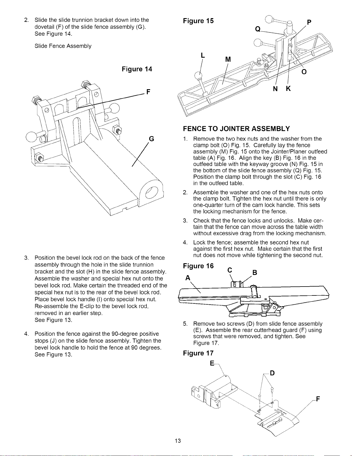
Figure 15 J_ p
L
M
O
,
,
F
G
Position the bevel lock rod on the back of the fence
assembly through the hole in the slide trunnion
bracket and the slot (H) in the slide fence assembly.
Assemble the washer and special hex nut onto the
bevel lock rod. Make certain the threaded end of the
special hex nut is to the rear of the bevel lock rod.
Place bevel lock handle (I) onto special hex nut.
Re-assemble the E-clip to the bevel lock rod,
removed in an earlier step.
See Figure 13.
Position the fence against the 90-degree positive
stops (J) on the slide fence assembly. Tighten the
bevel lock handle to hold the fence at 90 degrees.
See Figure 13.
N K
FENCE TO JOINTER ASSEMBLY
, Remove the two hex nuts and the washer from the
clamp bolt (O) Fig. 15. Carefully lay the fence
assembly (M) Fig. 15 onto the Jointer/Planer outfeed
table (A) Fig. 16. Align the key (B) Fig. 16 in the
outfeed table with the keyway groove (N) Fig. 15 in
the bottom of the slide fence assembly (Q) Fig. 15.
Position the clamp bolt through the slot (C) Fig. 16
in the outfeed table.
2. Assemble the washer and one of the hex nuts onto
the clamp bolt. Tighten the hex nut until there is only
one-quarter turn of the cam lock handle. This sets
the locking mechanism for the fence.
3. Check that the fence locks and unlocks. Make cer-
tain that the fence can move across the table width
without excessive drag from the locking mechanism.
4. Lock the fence; assemble the second hex nut
against the first hex nut. Make certain that the first
nut does not move while tightening the second nut.
Figure 16
C B
A
,
Remove two screws (D) from slide fence assembly
(E). Assemble the rear cutterhead guard (F) using
screws that were removed, and tighten. See
Figure 17.
Figure 17
13
Loading ...
Loading ...
Loading ...