Loading ...
Loading ...
Loading ...
,
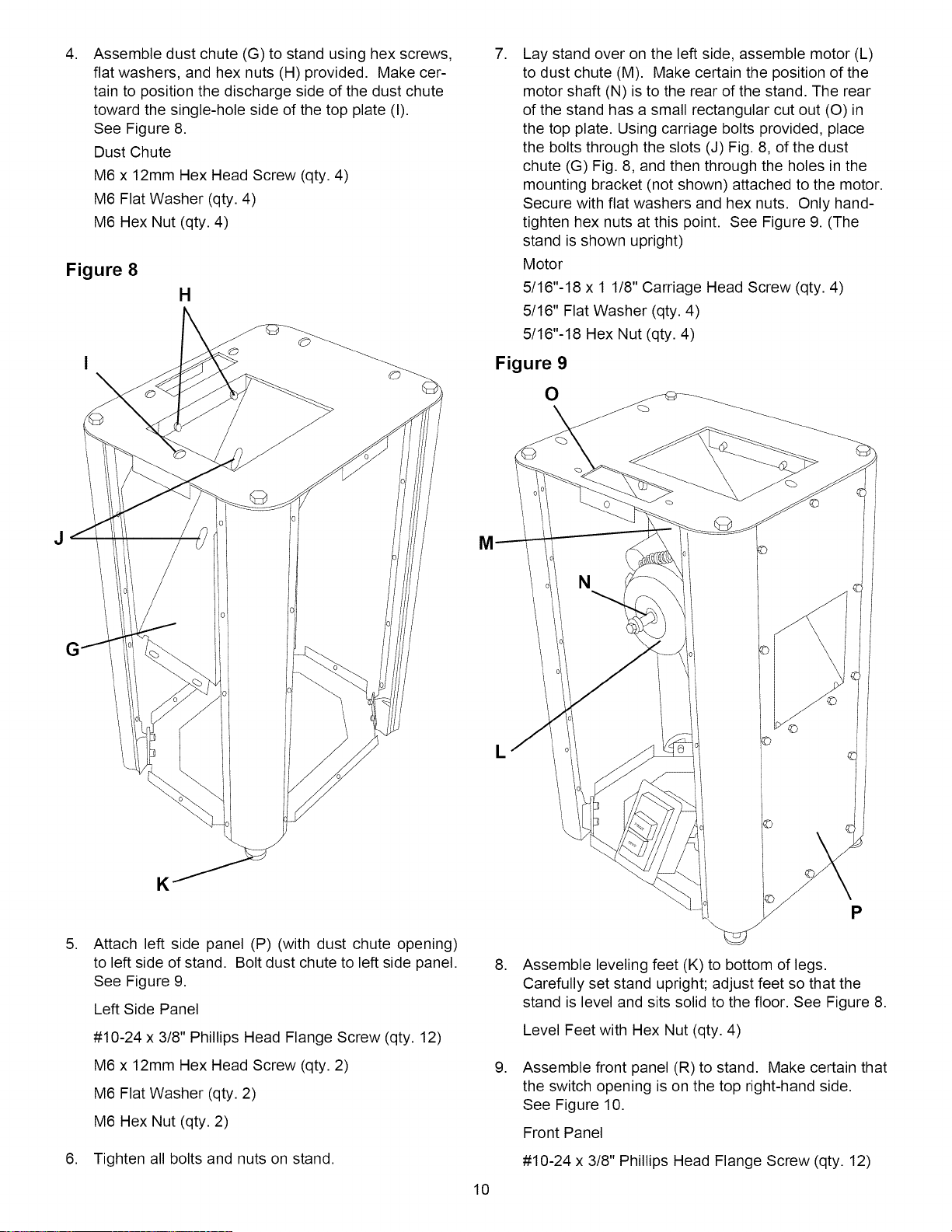
Assemble dust chute (G) to stand using hex screws,
flat washers, and hex nuts (H) provided. Make cer-
tain to position the discharge side of the dust chute
toward the single-hole side of the top plate (I).
See Figure 8.
Dust Chute
M6 x 12mm Hex Head Screw (qty. 4)
M6 Flat Washer (qty. 4)
M6 Hex Nut (qty. 4)
Figure 8
H
,
Lay stand over on the left side, assemble motor (L)
to dust chute (M). Make certain the position of the
motor shaft (N) is to the rear of the stand. The rear
of the stand has a small rectangular cut out (O) in
the top plate. Using carriage bolts provided, place
the bolts through the slots (J) Fig. 8, of the dust
chute (G) Fig. 8, and then through the holes in the
mounting bracket (not shown) attached to the motor.
Secure with flat washers and hex nuts. Only hand-
tighten hex nuts at this point. See Figure 9. (The
stand is shown upright)
Motor
5/16"-18 x 1 1/8" Carriage Head Screw (qty. 4)
5/16" Flat Washer (qty. 4)
5/16"-18 Hex Nut (qty. 4)
Figure 9
O
,
K
Attach left side panel (P) (with dust chute opening)
to left side of stand. Bolt dust chute to left side panel.
See Figure 9.
Left Side Panel
#10-24 x 3/8" Phillips Head Flange Screw (qty. 12)
M6 x 12mm Hex Head Screw (qty. 2)
M6 Flat Washer (qty. 2)
M6 Hex Nut (qty. 2)
6. Tighten all bolts and nuts on stand.
10
L
©
P
,
,
Assemble leveling feet (K) to bottom of legs.
Carefully set stand upright; adjust feet so that the
stand is level and sits solid to the floor. See Figure 8.
Level Feet with Hex Nut (qty. 4)
Assemble front panel (R) to stand. Make certain that
the switch opening is on the top right-hand side.
See Figure 10.
Front Panel
#10-24 x 3/8" Phillips Head Flange Screw (qty. 12)
Loading ...
Loading ...
Loading ...