High Low
OFF
ON
Plug-In Loop Detector
for the OmniControl™ Board
Part # AELD
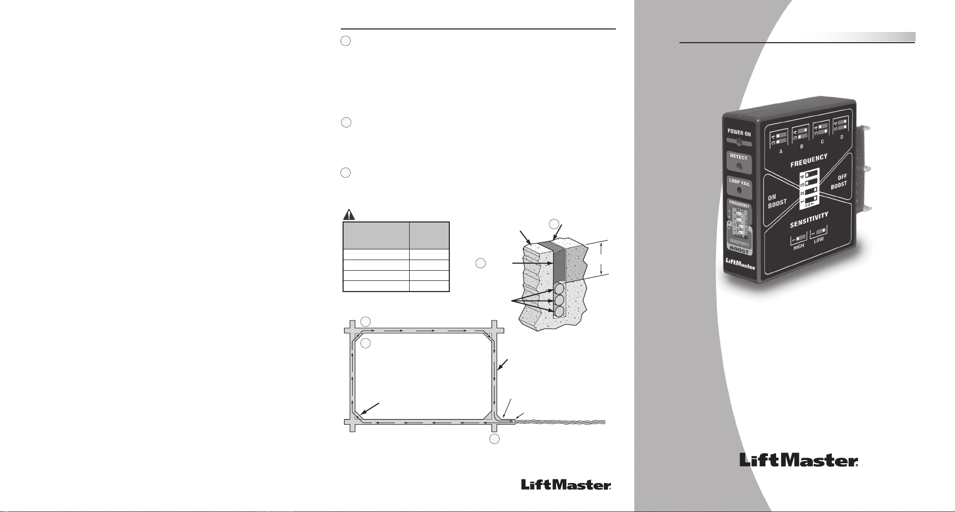
Dip Switch 1 - Sensitivity Level: The sensitivity is controlled by the setting of
switch1 on the front edge of the detector.
Note: Changing the sensitivity setting will automatically reset the detector.
Changing the frequency setting will not reset the detector. It is always necessary
to reset the detector after changing the frequency setting by t urning the gate
operator power off.
Dip Switch 2 - Boost on/off: When the switch 2 is off, the sensitivity boost is
disabled. When the switch 2 is on, the sensitivity boost is enabled. Boost enabled
will increase the sensitivity to detect high profile vehicles.
Dip Switch 3 & 4 - Frequency: The operating frequency of the detector is
controlled by the setting of switches 3 and 4 on the front edge of t
he
detector. Sometimes when
buried loops are in close proximity to each other, it
may be necessary to select different frequencies for each buried loo p to
avoid loop interference (commonly called crosstalk). The actual loop operating
frequency is a function of the size of the loop, the number of turns in the
loop, the length of the lead-in cable, and the setting of the frequency
switches (SW 3 & 4) . Therefore, setting one detector to Low and the other
to High may not provide any separation of o perating frequency. The most
accurate method of setting the o perati
ng fr
equency of multiple detectors is to
use a frequency meter connected to the loop to actually read the operating
frequency. The detectors fre quency should be adjusted so th at there is a
minimum of 5 kilohertz of separation between all adjacent loops.
LED Functions
– No Power
ON
– Power Applied
– No Presence
ON
– Presence Detected
– Loop OK
.5 Hz Flash
– Open Loop
3 Hz Flash
– Shorted Loop
Dip Switches
Dip Switch Functions
www.chamberlain.com
•
•
•
•
The “FAIL” LED indicates whether or not the loop is within tolerances. If the
loop is out of tolerance, the LED indicates whether the loop circuit was
shorted (3Hz Flash) or o pen (.5 Hz Flash). When the detector is detecting a
loop failure it will force a call output and the CALL LED will be on. If the loop
problem corrects itself, the detector will begin operating normally again and
the Fail LED will revert back to the Off state.
Failed Loop Diagnostics
Mark the loop layout on the pavement. Remove sharp inside corners that
can damage the loop wire insulation.
Determine the thickness of the pavement to ins ure that the depth of the
cut will not exceed the thickness of the pavement before attempting to
cut the loop slots. Set the saw to cut a depth (typically 2" to 2.5") that
will insure a minimum of 1"from the top of the loop wires to the pavement
surface. The saw width must be larger than the diameter of the loo p wire
to avoid d amage to the wire insulation when placed in the saw cut. Cut
the loo p, corner angles, and feeder slots. R emove all debris fro m the
saw slot with comp
ressed air. Che
ck that the bottom of the cut is smooth
and did not break though the thickness of the pavement.
Loop Installation
1
2
F
IRE
DE
PT
.
SYS
TEM ON
E
XIT
LOO
P
AL
A
RM
SE
NSOR
SAFETY
LOOP
OP
EN LE
FT
SENSORS
COMM
A
ND
PROC
ESSED
CEN
TE
R SA
FETY
EXIT
1
3
G B
MS L
INK
A
CENTER
SAFETY
EXIT
CENTER SAFETY EXIT
6 twists per ft from Loop
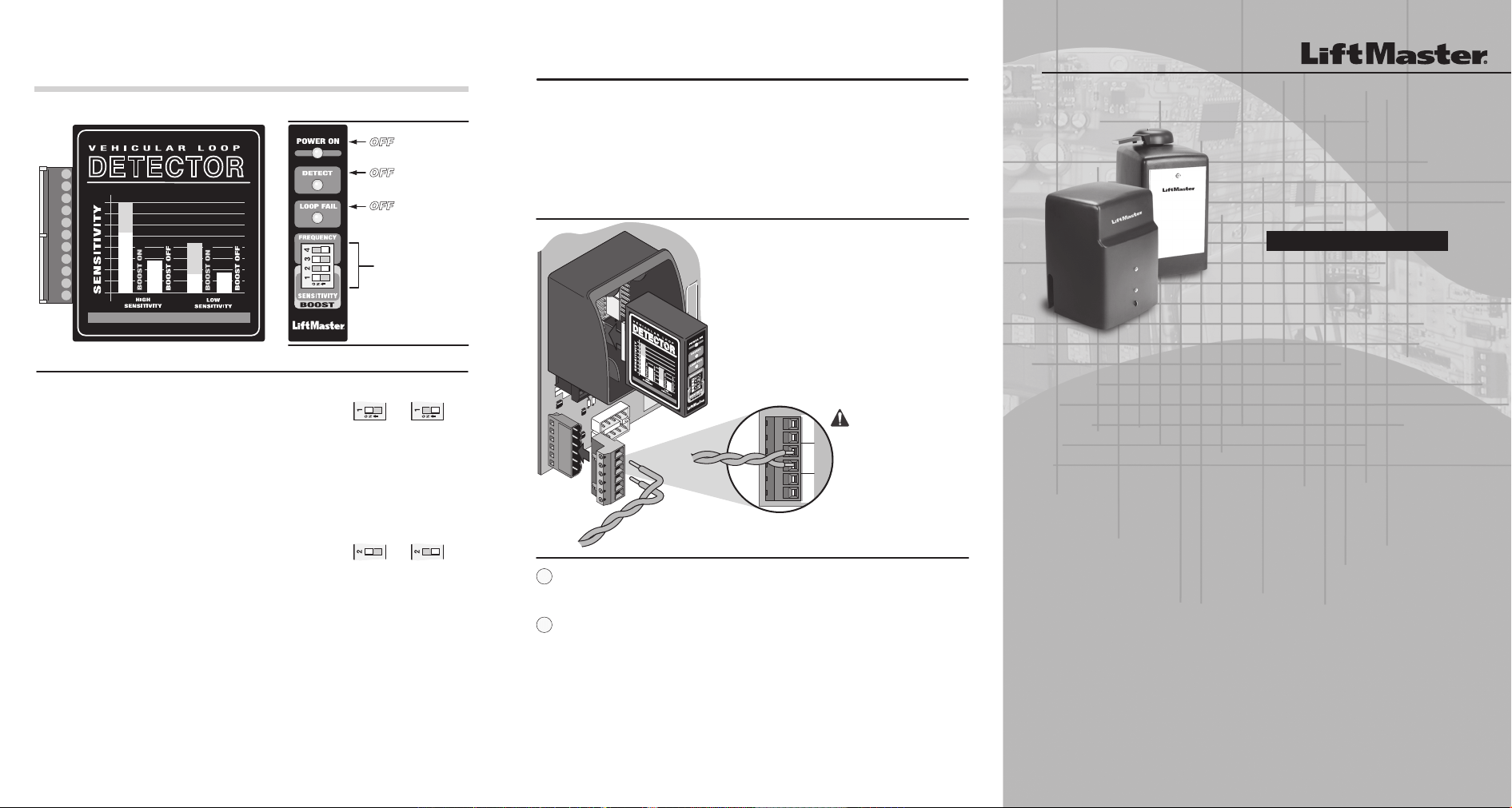
Turn the power
OFF
to the gate operator.
Plug in the loop detector in the desired slot
(i.e. center, safety, exit)
Plug in the terminal plug (provided) into terminal
J8 receptacle on the botto m left of the Omni board.
Bring twisted wires from the loop into the proper
terminal on the terminal plug (i.e. center, safety,
exit).
Turn the power back on.
Caution:
If using more than 1 loop
detector, set them to
different frequ encies.
(Refer to Dip Switch 3 & 4)
1.
2.
3.
4.
5.
Plug-In Loop Detector Installation
STRIK
E
OPEN
RE
VERSE
SEN
SOR
1
3
www.chamber
lain
.c
om
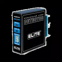
detector
vehicular loop
Plug-In Loop Detector
for Liftmaster
Enabled Controllers
MODEL # A E L D
now with BOOST CONTROL
1/8"to 1/4"
Saw Slot
Feeder Slot
End of Saw Cut
the loop saw slot for the required
number of turns. One turn shown.
(Refer to table above)
Remove Sharp
Inside Corners
These high quality loop detectors are for use with the
OmniControl™ Board available on LiftMaster’s commercial
line and other enabled controllers. With LiftMaster's
proven design and integration technology, these
component detectors will make installation of loop
detection systems simple.
845 Larch Avenue Elmhurst, Illinois 60126-1196
LiftMaster.com
Warning: LiftMaster does not warrant nor assumes liabilty for #AELD Loop Detectors installed in non LiftMaster enabled controllers.
for the OmniControl™ and other LiftMaster
#AELD enabled controllers.
#AELD Plug-In Loop Detection
now with BOOST CONTROL
01-50969D
The loop itself must be a continuous length of wire without any breaks or
splices. The loop wire can be 14, 16 or 18 gauge stranded wire with
either a cross-linked polyethylene (XLPE ) or polyester insulation.
Wrap the loop wire in the loop slot using a wooden stick or roller to
insert the wire to the bottom of the saw slot until the desired number of
turns are reached. (Caution: do not use a sharp object) Each turn of wire
must lay flat on top of the previous turn.
The wire must be twisted a minimum of 6 turns per foot from the end of
the feeder slot to the detector to minimize noise or interference. If a splice
is required in the feed
er cable, solde
r each splice and protect with a
moisture proof seal.
Apply the sealant. The sealant selected should have good adhering properties
with similar contraction and e xpansion characteristics as the pavement
material.
Loop Installation
10 feet - 13 feet
Loop
Perimeter
Important
Number
of Turns
4
314 feet - 26 feet
27 feet - 80 feet 2
181 feet and up
1
The wire is continuously wound in
The wire must be twisted together
6 twists per foot from the end of
the saw cut to the detector
4
1/8"to 1/4"
Saw Slot
Road Surface
Sealant
Loop Wire
(3 W ires Shown)
Min 1"
2
5
3
For Technical Support : 1-800-528-2806
5
4
3
© 2015, LiftMaster – all rights reserved
