Loading ...
Loading ...
Loading ...
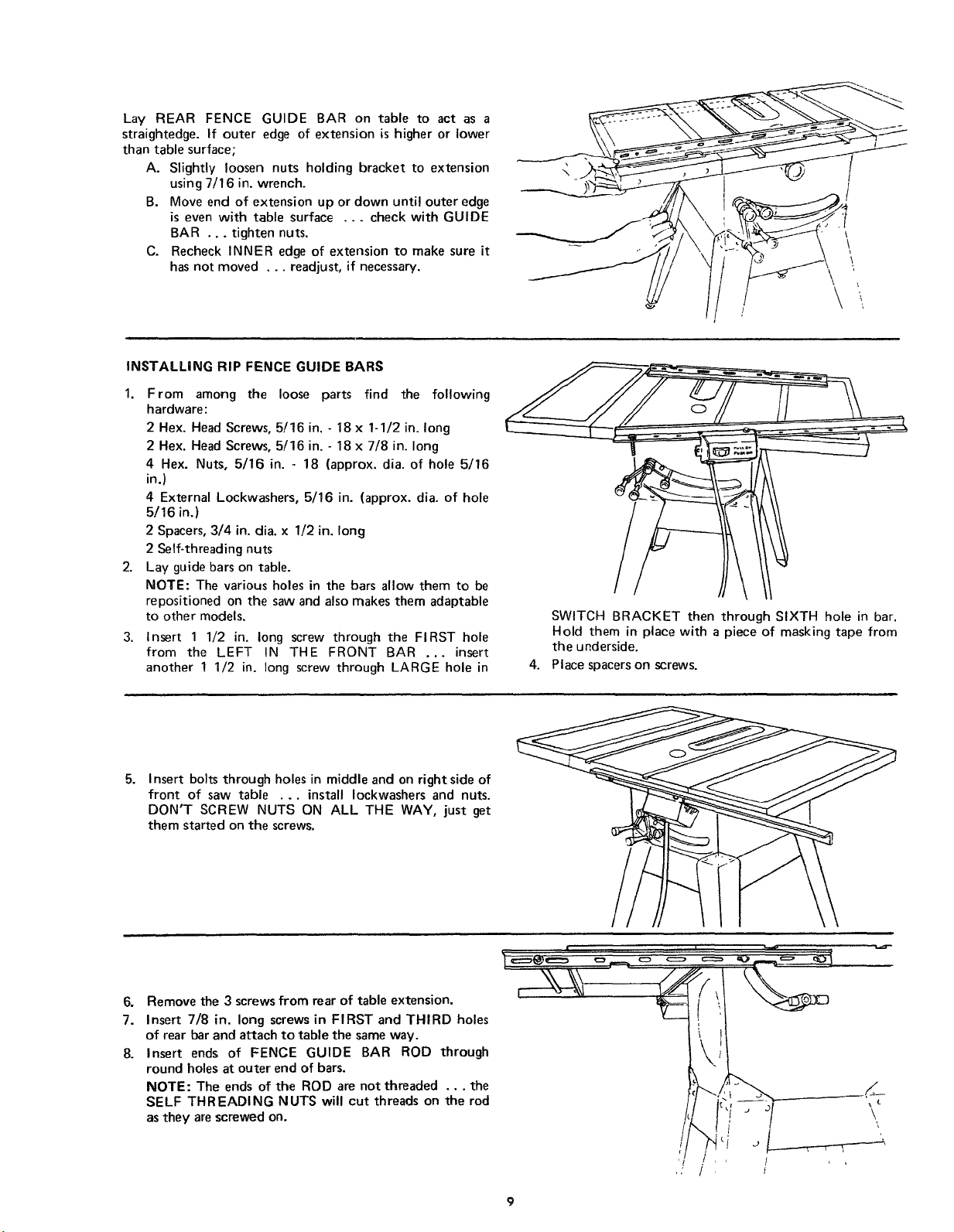
Lay REAR FENCE GUIDE BAR on table to act as a
straightedge. If outer edge of extension is higher or lower
than table surface;
A. Slightly loosen nuts holding bracket to extension
using 7/t6 in. wrench.
B. Move end of extension up or down until outer edge
is even with table surface ... check with GUIDE
BAR ... tighten nuts.
C. Recheck INNER edge of extension to make sure it
has not moved ... readjust, if necessary.
\
t
\
\
\
INSTALLING RIP FENCE GUIDE BARS
1. From among the loose parts find the following
hardware:
2 Hex. Head Screws, 5/16 in. - 18 x 1-1/2 in. long
2 Hex. Head Screws, 5/16 in. - 18 x 7/8 in. long
4 Hex. Nuts, 5/16 in. - 18 (approx. dia. of hole 5/16
in.)
4 External Lockwashers, 5/16 in. (approx. dia. of hole
5/16 in.)
2 Spacers, 3/4 in. dia. x 1/2 in. long
2 Self-threading nuts
2. Lay guide bars on table.
NOTE: The various holes in the bars allow them to be
repositioned on the saw and also makes them adaptable
to other models,
3. Insert 1 1/2 in. long screw through the FIRST hole
from the LEFT IN THE FRONT BAR ... insert
another 1 1/2 in. long screw through LARGE hole in
4.
SWITCH BRACKET then through SIXTH hole in bar.
Hold them in place with a piece of masking tape from
the underside.
Place spacers on screws.
5.
Insert bolts through holes in middle and on right side of
front of saw table ... install Iockwashers and nuts.
DON'T SCREW NUTS ON ALL THE WAY, just get
them started on the screws.
6.
7.
8°
Remove the 3 screws from rear of table extension,
Insert 7/8 in. long screws in FIRST and THIRD holes
of rear bar and attach to table the same way.
Insert ends of FENCE GUIDE BAR ROD through
round holes at outer end of bars.
NOTE: The ends of the ROD are not threaded ... the
SELF THREADING NUTS will cut threads on the rod
asthey are screwed on.
Loading ...
Loading ...
Loading ...