Loading ...
Loading ...
Loading ...
ASSEMBLY
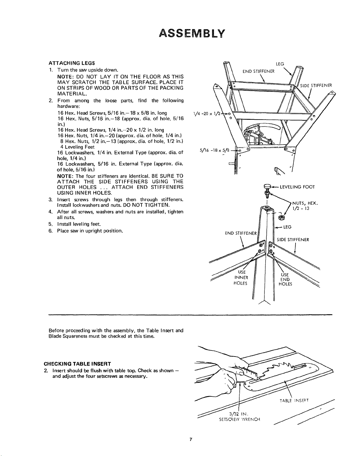
ATTACHgNG LEGS
1. Turn the saw upside down.
NOTE: DO NOT LAY IT ON THE FLOOR AS THIS
MAY SCRATCH THE TABLE SURFACE. PLACE IT
ON STRIPS OF WOOD OR PARTS OF THE PACKING
MATERIAL.
2. From among the loose parts, find the following
hardware:
16 Hex. Head Screws, 5/16 in.- 18 x 5/8 in. long
16 Hex, Nuts, 5/16 in.-18 (approx. dia. of hole, 5/16
in.)
16 Hex. Head Screws, 1/4 in.-20 x 1/2 in. long
16 Hex. Nuts, 1/4 in.-20 (approx. dia. of hole, 1/4 in.)
8 Hex. Nuts, 1/2 in.--13 (approx. dia. of hole, 1/2 in.)
4 Leveling Feet
16 Lockwashers, 1/4 in. External Type (approx. dia. of
hole, 1/4 in.)
16 Lockwashers, 5/16 in. External Type (approx. dia.
of hole, 5/16 in.)
NOTE: The four stiffeners are identical. BE SURE TO
ATTACH THE SIDE STIFFENERS USING THE
OUTER HOLES ... ATTACH END STIFFENERS
USING INNER HOLES.
3. Insert screws through legs then through stiffeners.
Install Iockwashers and nuts. DO NOT TIGHTEN.
4. After all screws, washers and nuts are installed, tighten
all nuts.
5. Install leveling feet.
6. Place saw in upright position.
END STIFFENER
LEG
;IDE STIFFENER
5/16 -18 x 5/8
END STIFFENER
j_LEVELING FOOT
NUTS, HEX.
I/2- _3
i..,_-.-LEG
SIDE STIFFENER
INNER
HOLES
END
HOLES
Before proceeding with the assembly, the Table Insert and
Blade Squareness must be checked at this time.
CHECKING TABLE INSERT
2. Insert should be flush with table top. Check asshown -
and adjustthe four setscrewsasnecessary.
3/32 IN.
SETSCREW WRENCH
Loading ...
Loading ...
Loading ...