Loading ...
Loading ...
Loading ...
ENGLISH
12
Use of CUTLINE LED Worklight System
(Fig. A)
CAUTION: Do not stare into worklight. Serious eye
injury couldresult.
NOTE: The battery must be charged and connected to the
mitersaw.
The CUTLINE LED Worklight System can be turned on by the
switch
14
. NOTE: The light will not automatically turn off if
the saw is not in use.
To cut through an existing pencil line on a piece of wood,
turn on the CUTLINE worklight system using the switch
14
(not with the main trigger), then pull down on the
operating handle
2
to bring the saw blade close to the
wood. The shadow of the blade will appear on the wood.
This shadow line represents the material that the blade will
remove when performing a cut. To correctly locate your
cut to the pencil line, align the pencil line with the edge
of the blade’s shadow. Keep in mind that you may have to
adjust the miter or bevel angles in order to match the pencil
lineexactly.
Your saw is equipped with a battery fault feature. The
CUTLINE worklight begins to flash when the battery is near
the end of its useful charge, or when the battery is too hot.
Charge the battery prior to continuing cutting applications.
Refer to Charging Procedure under Important
Safety Instructions for All Battery Packs for battery
charginginstructions.
Miter Control (Fig. A, H)
The miter lock knob
5
and miter latch button
6
allow
you to miter your saw to 47° right and 47° left. The miter
latch will automatically locate at 0˚, 15˚, 22.5˚, 31.62˚
and 45˚ both left and right. To miter the saw, unlock
the miter lock mechanism by rotating the miter lock
knob
5
counterclockwise and pulling up on the miter
latch buton
5
. Set the miter angle desired on the miter
scale
20
. Lock the miter lock knob by releasing the miter
latch button and rotating the miter lock knob clockwise
untiltight.
5
32
20
Fig. H
33
6
Bevel Lock Knob (Fig. A)
The bevel lock allows you to bevel the saw 47° to the left.
To adjust the bevel setting, turn the bevel lock knob
10
counterclockwise to loosen. To tighten, turn the bevel lock
knobclockwise.
CAUTION: Pinch hazard. Be sure to tighten bevel lock
knob before adjustingoverrides.
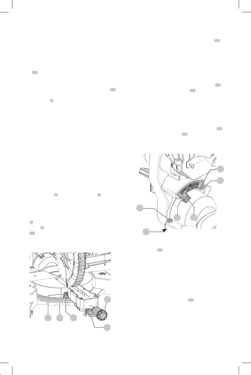
0° Bevel Stop Override (Fig. I)
The bevel stop override allows you to bevel the saw up to
3° to the right. Loosen the 0° bevel stop override nut
34
until the 0° bevel stop override screw
35
can freely rotate.
Turn the 0° bevel stop override bracket to allow the saw
to rotate past the zero bevel position, then retighten the
overridescrew.
45º Bevel Stop Override (Fig. I)
The bevel stop override allows you to bevel the saw up to
47° to the left. Loosen the 45° bevel stop override nut
36
until the 45° stop override screw
37
can freely rotate.
Turn the 45° bevel stop override bracket to allow the saw
to rotate past the 45° bevel position, then retighten the
overridenut.
FIg. I
37
39
34
35
36
40
Rail Lock Knob (Fig. A)
The rail lock knob
16
allows you to lock the saw head firmly
to keep it from sliding on the rails. This is necessary when
making certain cuts or when transporting thesaw.
Lock Down Pin (Fig. A)
WARNING: The lock down pin should be used only
when carrying or storing the saw. NEVER use the lock
down pin for any cuttingoperation.
To lock the saw head in the down position, push the saw
head down, push the lock down pin
19
in and release
the saw head. This will hold the saw head safely down for
moving the saw from place to place. To release, press the
saw head down and pull the pinout.
OPERATION
WARNING: To reduce the risk of serious personal
injury, turn tool off and remove the battery pack
before transporting, making any adjustments or
Loading ...
Loading ...
Loading ...