Loading ...
Loading ...
Loading ...
ENGLISH
10
indentations
8
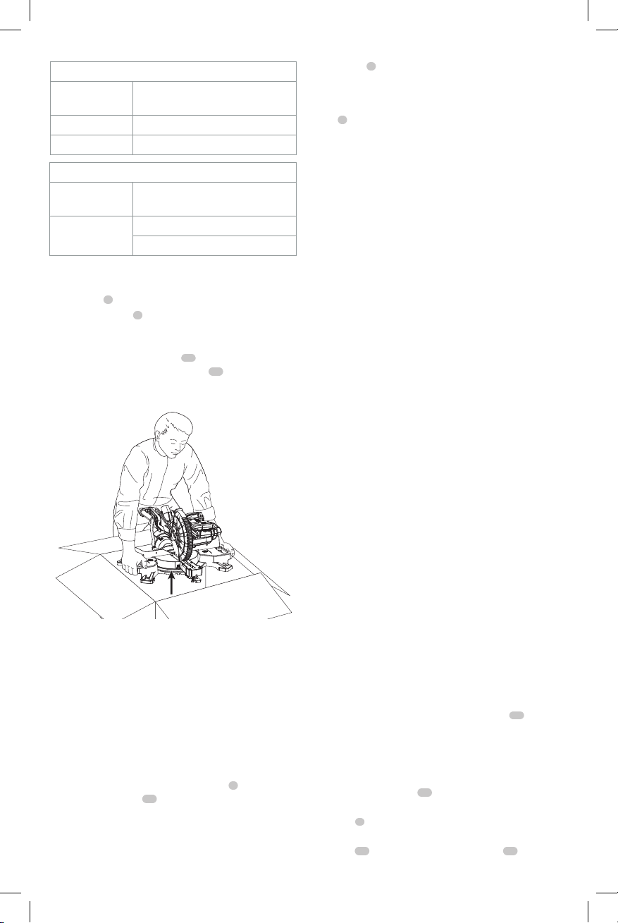
to transport the saw as seen in FigureA and
Figure D.
Bench Mounting (Fig. A)
Holes
3
are provided in all 4 feet to facilitate bench
mounting, as shown in FigureA. Always mount your
saw firmly to a stable surface to prevent movement. To
enhance the tool’s portability, it can be mounted to a piece
of 1/2" (12.7 mm) or thicker plywood which can then be
clamped to your work support or moved to other job sites
andreclamped.
NOTE: If you elect to mount your saw to a piece of plywood,
make sure that the mounting screws don’t protrude from
the bottom of the wood. The plywood must sit flush on the
work support. When clamping the saw to any work surface,
clamp only on the clamping bosses where the mounting
screw holes are located. Clamping at any other point will
interfere with the proper operation of thesaw.
CAUTION: To prevent binding and inaccuracy, be
sure the mounting surface is not warped or otherwise
uneven. If the saw rocks on the surface, place a thin
piece of material under one saw foot until the saw sits
firmly on the mountingsurface.
COMPONENTS (FIG. A)
WARNING: Never modify the power tool or any part
of it. Damage or personal injury couldresult.
Intended Use
This heavy duty miter saw is designed for professional wood
cuttingapplications.
DO NOT use under wet conditions or in presence of
flammable liquids orgases.
DO NOT let children come into contact with the tool.
Supervision is required when inexperienced operators use
thistool.
Changing or Installing a New Saw Blade
(Fig. E–G)
Refer to Saw Blades under Optional Accessories for correct
sawblade.
WARNING: To reduce the risk of serious personal
injury, turn tool off and remove the battery pack
before transporting, making any adjustments or
removing/installing attachments or accessories.
An accidental start-up can causeinjury.
CAUTION:
• Never depress the spindle lock button
25
while
the blade is under power orcoasting.
• Do not cut metal, masonry or fiber cement
product with this mitersaw.
Removing the Blade (Fig. A, E–G)
1. Remove battery pack
13
from thesaw.
2. Raise the arm to the upper position and raise the lower
guard
4
as far aspossible.
3. Loosen, but do not remove the guard bracket rear
screw
21
by fourrevolutions. The bracket
23
can be
Limits to Bevel Angle
Maximum Miter
Angle
Max Bevel Angle at Which Cut Can Be
Completed
48° Left Side Left Bevel: 40°
48° Right Side Left Bevel: 42.5°
Limits to Miter Angle
AT Maximum Bevel
Angle
Max Miter Angle at Which Cut Can Be
Completed
48° Left Side
Left Miter: 31.6°
Right Miter: 35°
Familiarization (Fig. A, D, L)
Open the box and lift the saw out by using the hand
indentations
8
in the base of the saw (Fig.D).
The miter lock knob
5
is not assembled for shipping.
Remove the miter lock knob from the packaging and screw
onto the saw. Refer to Figure A for position.
You saw has a built-in dust port
12
that allows either the
supplied, but not assembled, dust bag
42
or shop vacuum
system to be connected. Refer to Dust Extraction for
assembly instructions.
Fig. D
Place the saw on a smooth, flat surface such as a workbench
or strongtable.
Examine FigureA to become familiar with the saw and its
various parts. The section on adjustments will refer to these
terms and you must know what and where the partsare.
CAUTION: Pinch hazard. To reduce the risk of injury,
keep thumb underneath the operating handle when
pulling the handle down. The lower guard will move
up as the operating handle is pulled down, which
could cause pinching. The operating handle is placed
close to the guard for specialcuts.
Press down lightly on the operating handle
2
and pull
out the lock down pin
19
. Gently release the downward
pressure and hold the operating handle, allowing it to rise
to its full height. Use the lock down pin when carrying
the saw from one place to another. Always use the hand
Loading ...
Loading ...
Loading ...