Loading ...
Loading ...
Loading ...
46 | APPLICATION GUIDELINES
Single Zone Extended Piping Wall Mounted Engineering Manual
'XHWRRXUSROLF\RIFRQWLQXRXVSURGXFWLQQRYDWLRQVRPHVSHFL¿FDWLRQVPD\FKDQJHZLWKRXWQRWL¿FDWLRQ
©
/*(OHFWURQLFV86$,QF(QJOHZRRG&OLIIV1-$OOULJKWVUHVHUYHG³/*´LVDUHJLVWHUHGWUDGHPDUNRI/*&RUS
PLACEMENT CONSIDERATIONS
Indoor Unit
Selecting the Best Location for the Indoor Unit
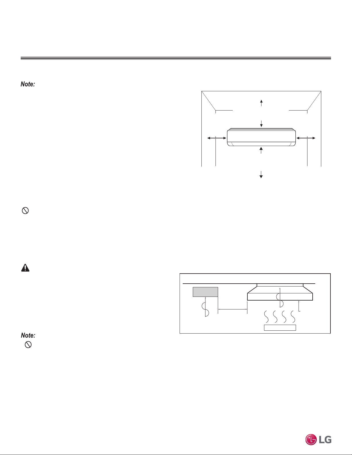
Figure 25: Extended Piping Indoor Unit Clearance Requirements.
More than 8 inches
(200 mm)
More than
4 inches
(100 mm)
More than
4 inches
(100 mm)
At least 6-1/2 feet
(2 m) from the floor
Follow required best practices when choosing an indoor location for the single
zone indoor unit.
Do’s
• Minimum clearance of indoor unit from the top of the unit to the ceiling
must be greater than 8 inches.
• Clearance gap between any wall or enclosure and the left or right side of
the unit must be greater than 4 inches. Ensure there is sufficient mainte-
nance space.
• Unit must be at least 6-1/2 feet from the floor for adequate clearance.
• Place the unit where drainage can be obtained easily. Condensation drain
must be conveniently routed away from the unit.
• Locate the indoor unit in a location where it can be easily connected to the
outdoor unit within allowable limits.
• Install unit on a strong, hard wall. Use a metal detector to locate studs in
the walls. Anchor unit following stud location to prevent damage to the wall.
Do Not’s
'RQRWLQVWDOOWKHXQLWQHDUDKHDWRUVWHDPVRXUFHRUZKHUHFRQVLGHUDEOHDPRXQWVRIRLOLURQSRZGHURUÀRXUDUHXVHG7KHVHPDWHULDOVZLOO
JHQHUDWHFRQGHQVDWHFDXVHDUHGXFWLRQLQKHDWH[FKDQJHUHI¿FLHQF\RUWKHGUDLQWRPDOIXQFWLRQ,IWKLVLVDSRWHQWLDOSUREOHPLQVWDOODYHQWLODWLRQIDQ
large enough to vent out these materials.)
(QVXUHWKHUHDUHQRREVWDFOHVWRDLUFLUFXODWLRQDURXQGWKHXQLWNHHSSURSHUGLVWDQFHVIURPFHLOLQJVGRRUZD\VÀRRUZDOOVHWF
• Do not install in an area where operation sound will disturb occupants--place the unit where noise prevention is taken into consideration.
• Do not install near doorway.
• Avoid installing the unit near high-frequency generators.
7KHXQLWPXVWQRWEHLQVWDOOHGZKHUHVXOIXULFDFLGDQGÀDPPDEOHRUFRU-
URVLYHJDVHVDUHJHQHUDWHGYHQWHGLQWRRUVWRUHG7KHUHLVULVNRI¿UH
explosion, and physical injury or death.
The unit will be damaged, will malfunction, and / or will not
operate as designed if installed in any of the conditions
listed.
• Indoor units (IDUs) must not be placed in an environment where the IDUs will be exposed to harmful volatile organic compounds
(VOCs) or in environments where there is improper air make up or supply or inadequate ventilation. If there are concerns about VOCs in the
environment where the IDUs are installed, proper air make up or supply and/ or adequate ventilation must be provided. Additionally, in build-
ings where IDUs will be exposed to VOCs consider a factory-applied epoxy coating to the fan coils for each IDU.
• If the unit is installed near a body of water, the installation parts are at risk of corroding. Appropriate anti-corrosion methods must be taken
for the unit and all installation parts.
Installing in an Area Exposed to Unconditioned Air
In some installation applications, areas (floors, walls) in some rooms will be exposed to unconditioned air (room will be above or next to an
unheated garage or storeroom). To countermeasure:
• Verify that carpet is or will be installed (carpet will increase the temperature by three [3] degrees).
• Add insulation between the floor joists.
• Install radiant heat or another type of heating system to the floor.
Install a ventilation fan
with sufficient capacity
Heat or steam source
Include enough
distance
Indoor Unit
Figure 26: Installing Near a Heat or Steam Source.
WARNING
Loading ...
Loading ...
Loading ...