Loading ...
Loading ...
Loading ...
PERFORMANCE DATA | 43
Performance Data
'XHWRRXUSROLF\RIFRQWLQXRXVSURGXFWLQQRYDWLRQVRPHVSHFL¿FDWLRQVPD\FKDQJHZLWKRXWQRWL¿FDWLRQ
©
/*(OHFWURQLFV86$,QF(QJOHZRRG&OLIIV1-$OOULJKWVUHVHUYHG³/*´LVDUHJLVWHUHGWUDGHPDUNRI/*&RUS
Cooling / Heating Correction Factors
For Single Zone Extended Piping Wall Mounted systems, calculate the equivalent length of the liquid line from the outdoor unit to the indoor
unit. Also, determine the elevation difference of the indoor unit above or below the outdoor unit. Find the corresponding cooling or heating
capacity correction factors as shown below. Multiply the correction factors by the cooling or heating capacity obtained from the capacity
tables using design conditions. The result is the NET cooling or heating capacity.
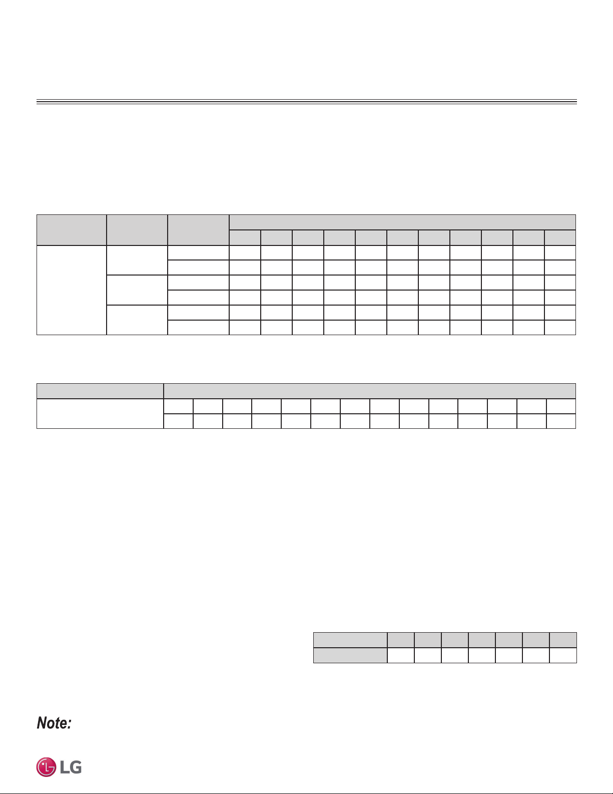
Table 23: ([WHQGHG3LSLQJ:DOO0RXQWHG&RROLQJDQG+HDWLQJ&DSDFLW\&RHI¿FLHQW)DFWRUV
Model No.
Operation
Mode
Piping Length (ft.)
16.4 24.6 32.8 49.2 65.6 82 98.4 114.8 131.2 147.6 164
Rate of Capacity
Change (%)
LS243HLV3
Cooling 100 100 99.6 98.7 97.8 96.9 96.0 95.1 94.3 93.4 92.5
Heating 100 100 99.8 99.3 98.9 98.4 98.0 97.5 97.1 96.6 96.2
LS303HLV3
Cooling 100 100 99.6 98.7 97.8 96.9 96.0 95.1 94.3 93.4 92.5
Heating 100 100 99.8 99.3 98.9 98.4 98.0 97.5 97.1 96.6 96.2
LS363HLV3
Cooling 100 100 99.6 98.7 97.8 96.9 96.0 95.1 94.3 93.4 92.5
Heating 100 100 99.8 99.3 98.9 98.4 98.0 97.5 97.1 96.6 96.2
EQUIPMENT SELECTION PROCEDURE
Correction Factors
Cooling and Heating Capacity Coefficient Factors.
Equivalent Piping Length for Piping Components
Table 24: Equivalent Piping Length for Elbows.
Component Size (Inches).
Elbow (ft.)
1/4 3/8 1/2 5/8 3/4 7/8 1 1-1/8 1-1/4 1-3/8 1-1/2 1-5/8 1-3/4 2-1/8
0.5 0.6 0.7 0.8 1.2 1.3 1.5 1.6 1.8 2.0 2.1 2.3 2.5 2.8
Altitude Correction Factor
The impact of air density must be considered on systems installed at a significant altitude above sea level, therefore, locally accepted altitude
correction factors using ASHRAE guidelines must be applied.
Defrost Correction Factor for Heating Operation
The outdoor unit heating capacity may need to be adjusted for frost accumulation on air-cooled systems. If design day conditions are below
the dewpoint of the surrounding air, frost may not be a problem and no correction factor is needed. In certain weather conditions, however,
frost may form and accumulate on the air-cooled outdoor unit coil and impact the coils ability to transfer heat. If significant frost accumulates
on the outdoor unit coil, a defrost algorithm will start automatically. The timing between defrost periods is determined by the system’s ability
to achieve a target head pressure value.
Capacity and AHRI ratings tables do not factor in capacity reduction when frost has accumulated on the condenser coil, nor during defrost
operation.
Integrated heating capacity values can be obtained using the formula:
A = B x C
Where:
A = Integrated Heating Capacity.
B = Value found in the Capacity Table.
C = Correction Factor for Frost Accumulation Factor (from table
at right).
Table 25: Outdoor Unit Frost Accumulation Factor (Heating).
1
Entering DB (ºF)
19.4 23.0 26.6 32.0 37.4 41.0 44.6
Derate Factor
0.98 0.95 0.93 0.86 0.93 0.96 1.0
1
At 85% outdoor air relative humidity.
The frost accumulation factor does not account for effects of snow accumulation restricting airflow
through the outdoor unit coil.
There will be a temporary reduction in capacity when frost / ice accumulates on the outside surface of the outdoor unit heat exchanger. The level of
capacity reduction depends on a number of factors, for example, outdoor temperature (°F DB), relative humidity (RH), and the amount of frost present.
Loading ...
Loading ...
Loading ...