Loading ...
Loading ...
Loading ...
24 | PRODUCT DATA
Single Zone Extended Piping Wall Mounted Engineering Manual
'XHWRRXUSROLF\RIFRQWLQXRXVSURGXFWLQQRYDWLRQVRPHVSHFL¿FDWLRQVPD\FKDQJHZLWKRXWQRWL¿FDWLRQ
©
/*(OHFWURQLFV86$,QF(QJOHZRRG&OLIIV1-$OOULJKWVUHVHUYHG³/*´LVDUHJLVWHUHGWUDGHPDUNRI/*&RUS
ELECTRICAL CONNECTIONS
• Terminal screws will become loose during transport. Properly tighten the terminal connections during installation or risk electric shock, physi-
cal injury, or death.
• Loose wiring will cause unit to malfunction, overheat, and catch fire, resulting in severe injury or death.
• Terminal screws will loosen during transport. Properly tighten the terminal connections during installation or risk equipment malfunction or
property damage.
• Loose wiring will cause unit malfunction, the wires to burnout or the terminal to overheat and catch fire. There is a risk of equipment malfunc-
tion or property damage.
A voltage drop will cause the following problems:
• Magnetic switch vibration, fuse breaks, or disturbance to the normal function of an overload protection device.
• Compressor will not receive the proper starting current.
WARNING
General Power Wiring / Communications Cable Guidelines
• Follow manufacturer’s circuit diagrams displayed on the inside of the control box cover.
• Confirm power source specifications.
• Properly ground the outdoor unit and the indoor unit per National Electrical Code (NEC) and local codes.
• Connect the wiring firmly so that the wires cannot be easily pulled out.
• Confirm that the electrical capacity is sufficient.
• Power supply to the outdoor unit must be selected based on NEC and local codes. Maximum allowable voltage fluctuation ±10% or name-
plate rated value.
• It is recommended that a circuit breaker is installed, especially if conditions could become wet or moist.
• Include a disconnect in the power wiring system. Add an air gap contact separation of at least 1/8 inch in each active (phase) conductor.
• Any openings where the field wiring enters the cabinet must be completely sealed.
Power Supply / Power Wiring
• LG Single Zone Extended Piping systems operate at 1Ø, 208-230V, 60Hz.
• Power wiring / power wiring gauge to the outdoor unit(s) must be solid or stranded, and must comply with all National Electrical Code
(NEC), UL, and local electrical codes.
• The indoor unit is powered by the outdoor unit. See the next page for communication / connection (power) cable specifications from the
outdoor unit to the indoor unit.
• Ground wire must be longer than the common power / communication wires.
• Connect the wiring firmly so the wires cannot be easily pulled out.
• Always match color codes of each wire and follow wiring diagram.
•
Do not install power wiring to the outdoor unit and the communication / connection (power) cable to the indoor unit in the same conduit.
Use separate conduits.
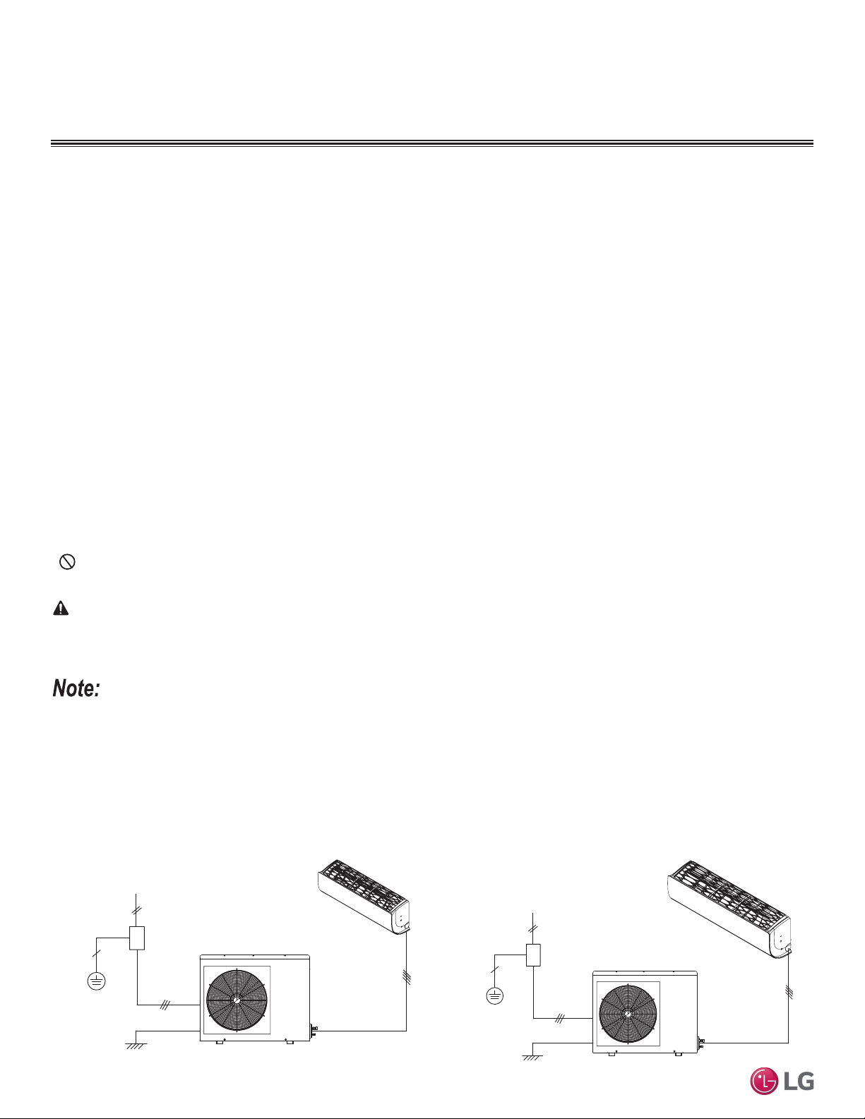
Figure 14: LS243HLV3 General Power / Communications System Sche-
matic.
Figure 15: LS303HLV3 and LS363HLV3 General Power / Communica-
tions System Schematic.
Indoor Unit
Outdoor Unit
Ground Wiring
Power Supply
Circuit Breaker
Indoor Unit
Outdoor Unit
Ground Wiring
Power Supply
Circuit Breaker
Loading ...
Loading ...
Loading ...