Loading ...
Loading ...
Loading ...
26 | PRODUCT DATA
Single Zone Extended Piping Wall Mounted Engineering Manual
'XHWRRXUSROLF\RIFRQWLQXRXVSURGXFWLQQRYDWLRQVRPHVSHFL¿FDWLRQVPD\FKDQJHZLWKRXWQRWL¿FDWLRQ
©
/*(OHFWURQLFV86$,QF(QJOHZRRG&OLIIV1-$OOULJKWVUHVHUYHG³/*´LVDUHJLVWHUHGWUDGHPDUNRI/*&RUS
ELECTRICAL CONNECTIONS
• Use a conduit for the communications cable / power wiring from the outdoor unit to the indoor unit.
• Make sure the communications cable / power wiring from the outdoor unit to the indoor unit, and the power wiring to the outdoor unit are
separate, otherwise, the outdoor unit operation will be affected by electrical noise and will malfunction or fail.
Controller Options
Single Zone Extended Piping Wall Mounted systems include a wireless handheld remote controller (Part
No. AKB74955602). Optional LG-suppled wired controllers are available. See “Functions, Controls,
Options”, or contact an LG representative for more information.
Wireless Handheld Remote Controller features:
• Display Panel: Displays operation conditions.
• On / Off Button: Turns system operation on and off.
• Mode Button: Selects the operation mode: Cooling, Heating, Auto, Dry (Dehumidification), or Fan.
• Temp Up / Down Buttons: Adjusts the desired room temperature in the different modes.
• Fan Speed Button: Sets desired fan speed.
• Reset: Initializes the handheld remote control settings.
Wired Controller Connections
Optional controllers (see “Functions, Controls, Options”, or contact an LG representative for more
information) can connect to the Extended Piping Wall Mounted indoor unit in one of two different ways:
1. LG Wired Remote Extension Cable with Molex plug (PZCWRC1; sold separately) that connects to the
CN-REMO terminal on the indoor unit PCB.
2. Field-supplied controller cable that connects to the indoor unit terminal block (must be at least UL2547
or UL1007, and at least FT-6 rated if local electric and building codes require plenum cable usage).
Communication cable from indoor unit to remote controller(s) is to be 22 AWG, 3-conductor, twisted,
stranded, unshielded. Wiring must comply with all applicable local and national codes.
Figure 20: AKB74955602 Wire-
less Handheld Remote Controller.
Display
Button
Screen
*
*
*
Reset
Verify the connectors are properly inserted.
C/BOX Cable (Plug type)
Extension cable
To Indoor Unit
CN-REMO
Terminal
TEMP
FAN
SPEED
OPER
MODE
:KHQXVLQJ¿HOGVXSSOLHGFRQWUROOHUFDEOHPDNHVXUHWRFRQQHFWWKH\HO-
low to yellow (communications wire), red to red (12V power wire), and
black to black (ground wire) terminals from the remote controller to the
indoor unit terminal blocks.
Figure 21: PZCWRC1 LG Wired Remote Extension Cable.
Figure 22: Wired Controller Connection (Example Only).
Indoor Unit Terminal
BR BL
RD
GR/YL
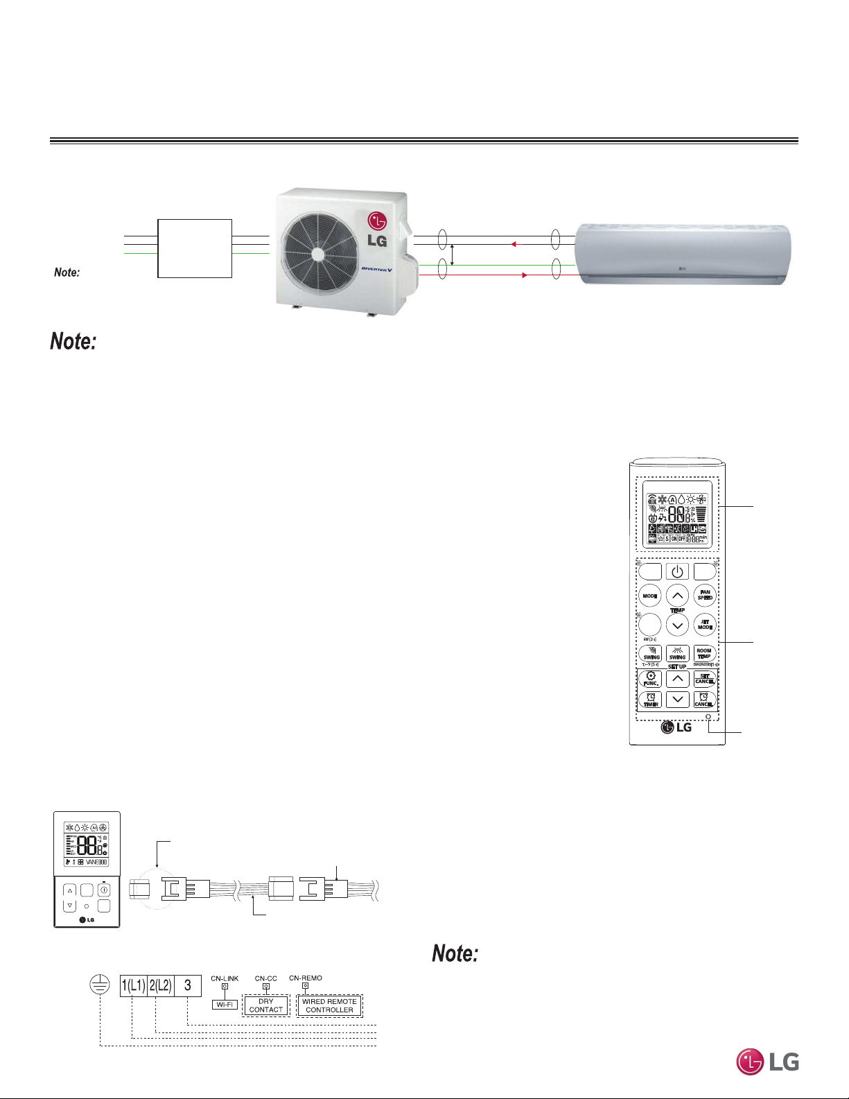
Figure 23: Schematic of a Single Zone System When the Wiring is GREATER THAN 130 Feet.
Power
Supply
1(L1) (Power, L)
2(L2) (Neutral, N)
G (Ground)
Power Flow: L ĺ N
Diagram is an example of communication and power
cables when the wiring is GREATER THAN 130 feet.
Terminals may be labeled differently depending on the model.
Outdoor and Indoor Unit a
pp
earances ma
y
var
y
de
p
endin
g
on the model.
Communication Flow: Comm ĺ N
3 (Communications)
GREATER THAN 130 feet: Must Separate Communications and Ground (G) Cable from the Power
(1[L1]) and Neutral (2[L2]) Cable at Least Two (2) Inches.
At Least Two (2) Inches
Loading ...
Loading ...
Loading ...