Loading ...
Loading ...
Loading ...
Determine vent path
• Select the route that will provide the straightest and most
direct path outdoors.
• Plan the installation to use the fewest number of elbows and
turns.
• When using elbows or making turns, allow as much room as
possible.
• Bend vent gradually to avoid kinking.
• Use the fewest 90 ° turns possible.
Determine vent length and elbows needed for best
drying performance
• Use the Vent system chart below to determine type of vent
material and hood combinations acceptable to use.
• NOTE: Do not use vent runs longer than specified in the Vent
system chart. Exhaust systems longer than specified will:
• Shorten the life of the dryer.
• Reduce performance, resulting in longer drying times and
increased energy usage.
The Vent system chart provides venting requirements that will
help to achieve the best drying performance.
Vent system chart
NOTE: Side and bottom exhaust installations have a 90° turn
inside the dryer. To determine maximum exhaust length, add one
90 ° turn to the chart.
Number of Type of Box or Angled
90 ° turns vent Louvered hoods
or elbows hoods
0 Rigid metal 64 ft (20 m) 58 ft (17.7 m)
Flexible metal 36 ft (11 m) 28 ft (8.5 m)
1 Rigid metal 54 ft (16.5 m) 48 ft (14.6 m)
Flexible metal 31 ft (9.4 m) 23 ft (7 m)
2 Rigid metal 44 ft (13.4 m) 38 ft (11.6 m)
Flexible metal 27 ft (8.2 m) 19 ft (5.8 m)
3 Rigid metal 35 ft (10.7 m) 29 ft (8.8 m)
Flexible metal 25 ft (7.6 m) 17 ft (5.2 m)
4 Rigid metal 27 ft (8.2 m) 21 ft (6.4 m)
Flexible metal 23 ft (7 m) 15 ft (4.6 m)
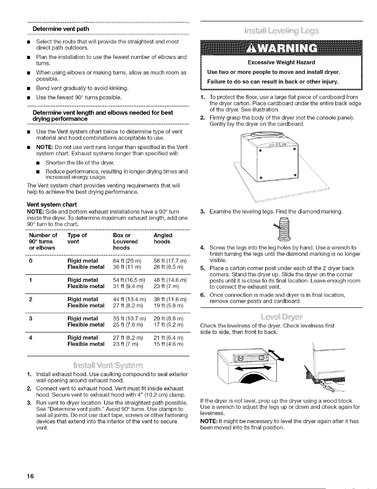
1. To protect the floor, use a large flat piece of cardboard from
the dryer carton. Place cardboard under the entire back edge
of the dryer. See illustration.
2. Firmly grasp the body of the dryer (not the console panel).
Gently lay the dryer on the cardboard.
\\ \\,
3.
Examine the leveling legs. Find the diamond marking.
4. Screw the legs into the leg holes by hand. Use a wrench to
finish turning the legs until the diamond marking is no longer
visible.
5. Place a carton corner post under each of the 2 dryer back
corners. Stand the dryer up. Slide the dryer on the corner
posts until it is close to its final location. Leave enough room
to connect the exhaust vent.
6.
Once connection is made and dryer is in final location,
remove corner posts and cardboard.
Check the levelness of the dryer. Check levelness first
side to side, then front to back.
1.
2.
3.
Install exhaust hood. Use caulking compound to seal exterior
wall opening around exhaust hood.
Connect vent to exhaust hood. Vent must fit inside exhaust
hood. Secure vent to exhaust hood with 4" (10.2 cm) clamp.
Run vent to dryer location. Use the straightest path possible.
See "Determine vent path." Avoid 90 ° turns. Use clamps to
seal all joints. Do not use duct tape, screws or other fastening
devices that extend into the interior of the vent to secure
vent.
If the dryer is not level, prop up the dryer using a wood block.
Use a wrench to adjust the legs up or down and check again for
levelness.
NOTE: It might be necessary to level the dryer again after it has
been moved into its final position.
16
Loading ...
Loading ...
Loading ...