Loading ...
Loading ...
Loading ...
8
Installation
The Building Regulations state that “The discharge
pipe (D2) from the tundish should terminate in a
safe place where there is no risk to persons in the
vicinity of the discharge.”
Examples of acceptable discharge arrangements
are:
- “to a trapped gully with the end of the pipe
belowaxedgratingandabovethewaterseal;
- downward discharges at low level; i.e. up to
100mm above external surfaces such as car
parks, hard standings, grassed areas etc. are
acceptable providing that a wire cage or similar
guard is positioned to prevent contact, whilst
maintaining visibility; and,
- discharges at high level: e.g. into a metal
hopper and metal downpipe with the end of the
discharge pipe clearly visible or onto a roof
capable of withstanding high temperature
discharges of water and 3m from any plastic
guttering system that would collect such
discharges.”
Note: As the discharge would consist of high
temperature water and steam, asphalt,
roongfeltandnon-metallicrainwatergoods
may be damaged by such discharges.
5.4.3 Termination of Discharge Pipe
5.5 Limitations
Due to the operating temperatures of direct
electric cylinders the water hardness can
considerablyinuencethelongevityofthe
immersion heater element. Please consult local
water board for advice on maintenance intervals.
5.6 Product Disposal
This product has been manufactured from
mostly recyclable materials. At the end of
the product’s life, it should be disposed of
at a Local Authority Recycling Centre.
Materials:
• Inner Cylinder - Duplex Stainless Steel
• Outer Cladding - Black HIPS/ABS
• Inlet/Outlet Pipe - Stainless Steel
• Coils - Corrugated Stainless Steel
• Insulation - 60mm PU Foam (GWP =1, ODP =0)
• T&P Valve - Brass & LDPE
• Immersion Heater - Incoloy and brass
• Tundish - LDPE
6 Installation
Install the cylinder in an appropriate location,
ensuring all of the recommendations have been
considered (see chapter 5.2).
6.1 Cold Water Inlet with Inlet Group
6.1.1 Correctly Site the Cylinder
The inlet group regulates the pressure of the
incoming mains water supply to the cylinder and
removes any debris that might be water borne.
Between the inlet group and the cold
water inlet on the cylinder NO isolating
devicemaybetted,asbydoingso
important safety devices could be isolated!
6.1.2 Install the Inlet Group
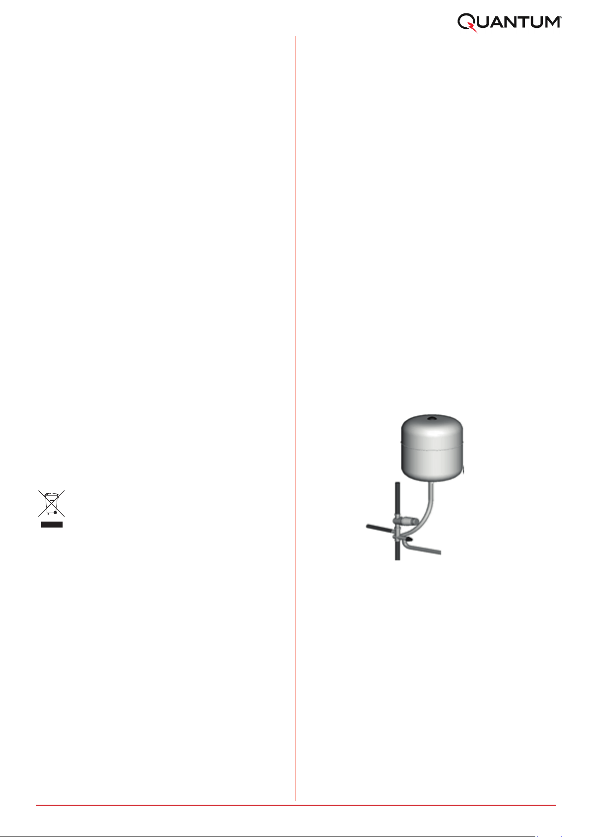
The expansion vessel is mandatory on all
Quantum cylinders and can be connected directly
tothecoldwaterinletgroup,utilisingtheexible
hose supplied with the vessel. The expansion
vesselshouldalwaysbettedinaccordancewith
the manufacturer’s instructions. No isolating
devicemustbettedbetweenthewatercylinder
and the cold water inlet group. Furthermore, it is
recommended to mount the vessel higher than
the cylinder to avoid having to drain the cylinder
when maintaining and replacing the expansion
vessel.
6.1.3 Expansion Vessel
Figure 2: Connection of the expansion vessel
to the inlet group
It is important to check the pre-charge pressure
oftheexpansionvesselmembranebeforelling
the cylinder. This has been factory set to 3 bar.
The pre-charge should be greater than or equal to
3bar.
Note: The expansion vessel must be installed
to the side of the expansion relief valve on
the inlet group. To do this, the blanking plug
must be removed and the expansion vessel
connected, as shown in Figure 3.
Loading ...
Loading ...
Loading ...