Loading ...
Loading ...
Loading ...
10
Installation
6.4 Immersion Heaters
The main immersion heater and boost immersion
heater supplied with this cylinder come pre-wired.
A supply cable shall be connected to the unit
through the entry in the electrical enclosure, at
the bottom of the cylinder. Details are given on
how to do this in section 6.5 of this manual. The
electrical wiring diagram for the product is shown
in Figure 8.
The immersion heater incorporates an
independent non self-resetting over temperature
cut-out. Should the over temperature cut-out
operate, the reset pin will be pushed upwards,
and become level or slightly proud of the cover
at the position marked “Safety”, and the water in
the cylinder will fail to heat. This denotes a fault
somewhere in the system and an appropriate
investigation shall be carried out before the
cut-out is reset. Use a suitable sized implement
to reset the pin by pushing it hard into its original
position.
Should it be necessary to remove the
thermostat from the immersion
element, ensure that the contacts are
re-ttedcorrectlyintothepositionson
the element. Failure to do so carries
the risk of overheating the contacts
and thus damaging the appliance.
The immersion heater thermostat must not be
opened under any circumstances.
Figure 4: Correct Operation of Immersion Heater
Thecylindermustbelledwith
water before switching on the
immersion heater. Failure to do so
will damage the element and void any
guarantee on the product.
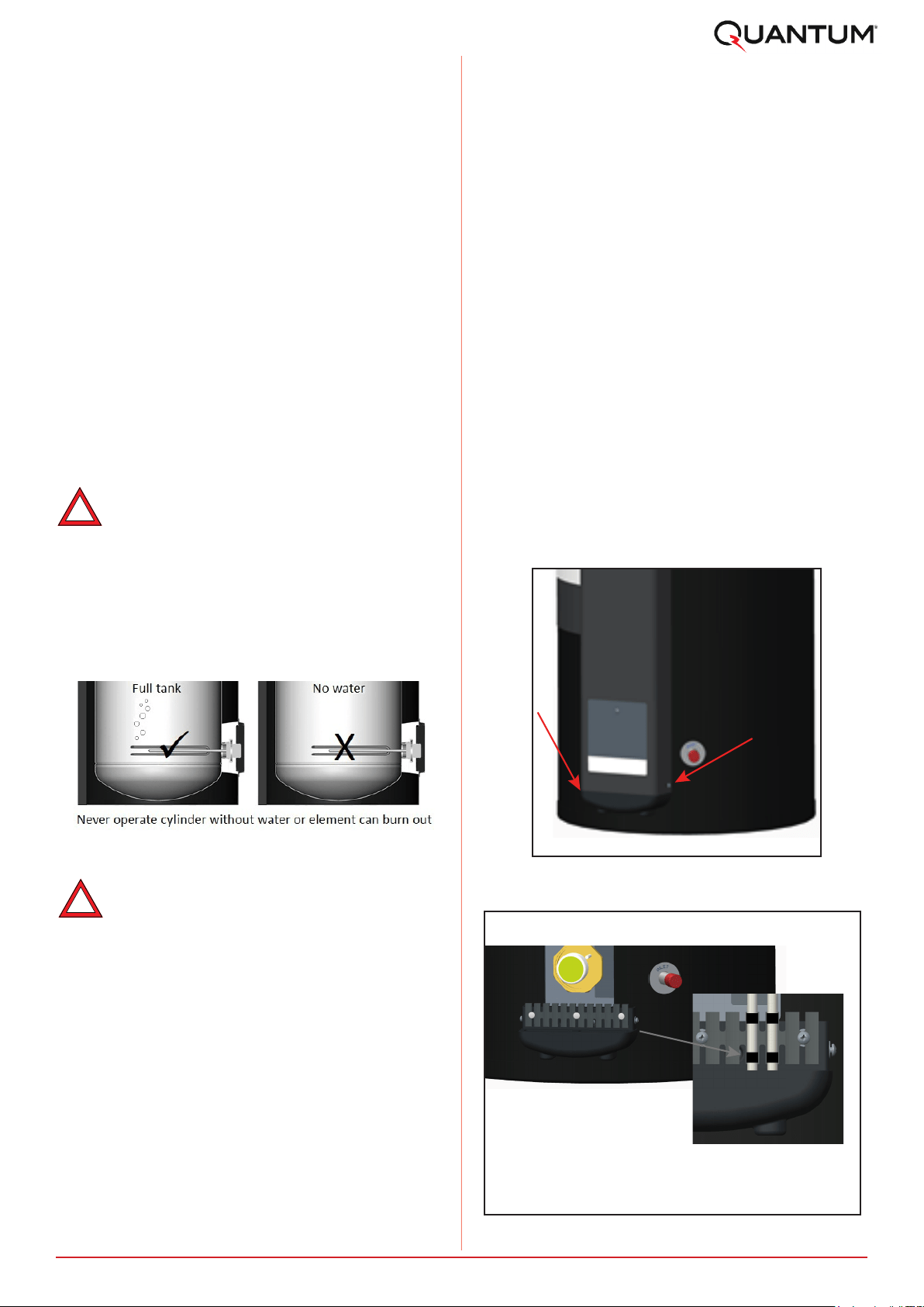
6.5.1 Access Connections
To access the electrical connection panel, remove
the enclosure hood by removing the retaining
screws on the sides, as shown in Figure 5. Please
take care when removing the hood, as it is
connected to the cylinder via an earth cable and
a cable to the UI. The water cylinder requires two
supply cables. Where an off-peak supply circuit is
available this can be used and connected to the
‘switched’ supply connections marked on the
terminal block. Where only one wiring circuit is
available two supplies from this circuit are
required. Both supplies must be connected
through a separate double pole isolating switch
which must have a contact separation of at least
3mm in all poles. The cables shall be connected to
the unit through the entry in the electrical
enclosure, at the bottom of the cylinder and
should be connected to the cylinder as shown in
Figure 6.
The cables should be cable-tied securely to the
strain relief provided and if required cable-tied to
the existing cabling on the right-hand side.
The protective tape should be removed from the
contact area between the hood and the cylinder
cladding before commissioning as per Figure 6.
Figure 5: Retaining Screw Positions
6.5 Electrical Connection
The water cylinder has to be connected in
accordance with IEE Wiring Regulations and the
installer carrying out the work has to be suitably
qualied.Beforeconnectingthecylinder,verify
that all the wiring connections on each of the
elements and thermostats have been installed
correctly, that they are secure and that none of
the wires are damaged.
The electrical installation of this cylinder can be
set-up for permanent supply or switched supply
(peak and off-peak). For information on how to
correctly wire either set-up please see Figures 7
or 8 in Section 6.5.2.
Remove protective tape before
commossioning.
The two supply cables must be
fed through the bottom of the
enclosure.
Cable ties [supplied] must be
used to secure the supply
cables into position along the
cable clamp
Figure 6: Supply Cable Anchorage
!
!
Loading ...
Loading ...
Loading ...