
Loading ...
Loading ...
Loading ...
EN
W415-1285 / L / 10.25.21
51
adjustments
VENTURI ADJUSTMENT
CHART
NG 1/16” (1.6mm)
P 5/16” (8mm)
12.0 adjustments
12.1 pilot burner adjustment
12.2 venturi adjustment
Adjust the pilot screw to provide properly sized fl ame. Turn in a clockwise direction to reduce the gas fl ow.
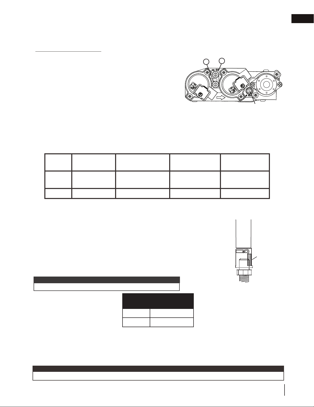
Check Pressure Readings:
Inlet pressure can be checked by turning screw (A) counter-
clockwise 2 or 3 turns and then placing pressure gauge tubing
over the test point. Gauge should read as described on the chart
below. Check pressure with main burner operating on “HI”.
Outlet pressure can be checked the same as above using screw
(B). Gauge should read as described on the chart below. Check
pressure with main burner operating on “HI”.
After taking pressure readings, be sure to turn screws
clockwise fi rmly to reseal. Do not overtorque.
Leak test with a soap and water solution.
Prior to pilot adjustment, ensure that the pilot assembly has not been painted. If overspray or painting of
the pilot assembly has occurred remove the paint from the pilot assembly, or replace. Fine emery cloth or a
synthetic scrub pad (such as Scotch-Brite
™)
can be used to remove the paint from the pilot hood, electrode
and fl ame sensor.
25.1
INSERT PILOT ASSEMBLY
*Maximum inlet pressure not to exceed 13”
Pressure Natural Gas
(inches)
Natural Gas
(millibars)
Propane
(inches)
Propane
(millibars)
Inlet
*7”
(minimum 4.5”)
17.4mb
(minimum 11.2mb)
13”
(minimum 11”)
32.4mb
(minimum 27.4mb)
Outlet
3.5” 8.7mb 10” 24.9mb
This appliance has an air shutter that has been factory set open according to
the chart below:
Regardless of venturi orientation, closing the air shutter will cause a more
yellow flame, but can lead to carbonization. Opening the air shutter will cause
a more blue flame, but can cause flame lifting from the burner ports. The flame
may not appear yellow immediately; allow 15 to 30 minutes for the final flame
colour to be established.
AIR SHUTTER ADJUSTMENT MUST ONLY BE DONE BY A QUALIFIED
INSTALLER.
AIR
SHUTTER
OPENING
VENTURI
BURNER
ORIFICE
33.1
It is important that the orifice is securely inserted into the venturi.
note:
12.3 restricting vertical vents
16.6A
Vertical installations may display a very active fl ame. If this appearance is not desirable, the vent exit must be
restricted using a restrictor vent kit. Refer to the “replacement parts” section of the owner’s manual for the
appropriate kit. This will reduce the velocity of the exhaust gases, slowing down the fl ame pattern and creating a
more traditional gentle fl ame appearance. Specifi c instructions are included with the kit.
If the appliance has been reduced to 4/7" venting only, use an RP4 to restrict vertical venting.
note:
A
B
PILOT SCREW
Loading ...
Loading ...
Loading ...