
Loading ...
Loading ...
Loading ...
EN
W415-1285 / L / 10.25.21
25
venting installation
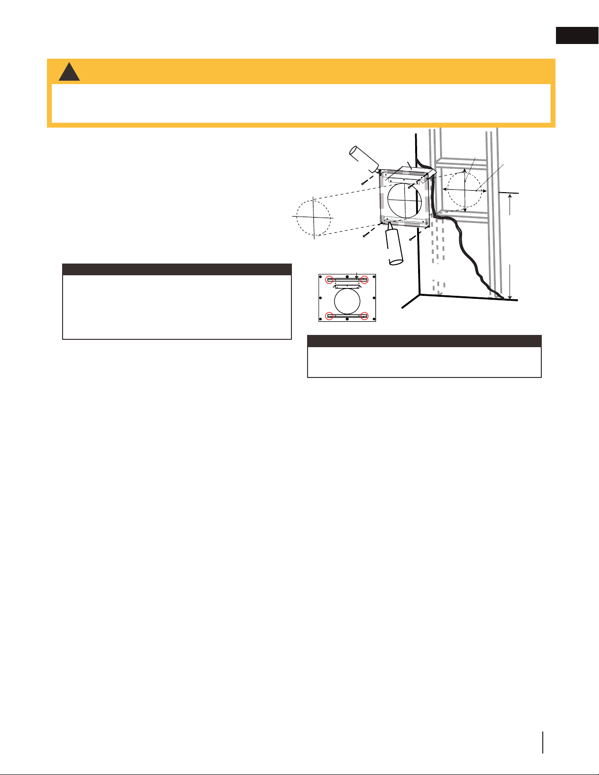
5.1 horizontal installation
16.2A
This application occurs when venting through an exterior
wall. Having determined the correct height for the air
terminal location, cut and frame a hole in the exterior wall,
as illustrated, to accommodate the fi restop assembly. Dry
fi t the fi restop assembly before proceeding to ensure the
brackets on the rear surface fi t to the inside surface of the
horizontal framing.
The vent shield must be installed to the full depth of the
combustible wall. The length of the vent shield may cut
shorter for combustible walls that less than 6” (152mm)
thick.
A. Apply a bead of caulking (not supplied) around the
corner edge of the inside surface of the fi restop
assembly, fi t the fi restop assembly to the hole and
secure using 4 screws.
B. Once the vent pipe is installed in its fi nal position, apply red RTV silicone (W573-0002) (not supplied)
between the pipe and the fi restop.
Bend the tabs for reduced side clearances or move
the shield for reduced top clearances. Do not fi ll
the air space between the fi restop spacer and the
exterior wall with any type of insulating material (i.e.
spray foam).
note:
DETERMINE
THE
CORRECT
HEIGHT
CAULKING
FIRESTOP
SPACER
VENT
SHIELD
FINISHING
MATERIAL
CAULKING
note:
The above is for illustration purposes only. Vents do
not always pass through center of frame.
ADD
HEIGHT
ADD
WIDTH
Determine
the
correct
height
Firestop
spacer
Vent
shield
Finishing
material
Caulking
A
C
C
• The fi restop assembly must be installed with the vent shield to the top.
• Terminals must not be recessed into a wall or siding more than the depth of the return fl ange of the mounting
plate.
!
WARNING
14”
(35.6CM)
height
14”
(35.6CM)
width
Loading ...
Loading ...
Loading ...