
Loading ...
Loading ...
Loading ...
W415-1285 / L / 10.25.21
EN
28
venting installation
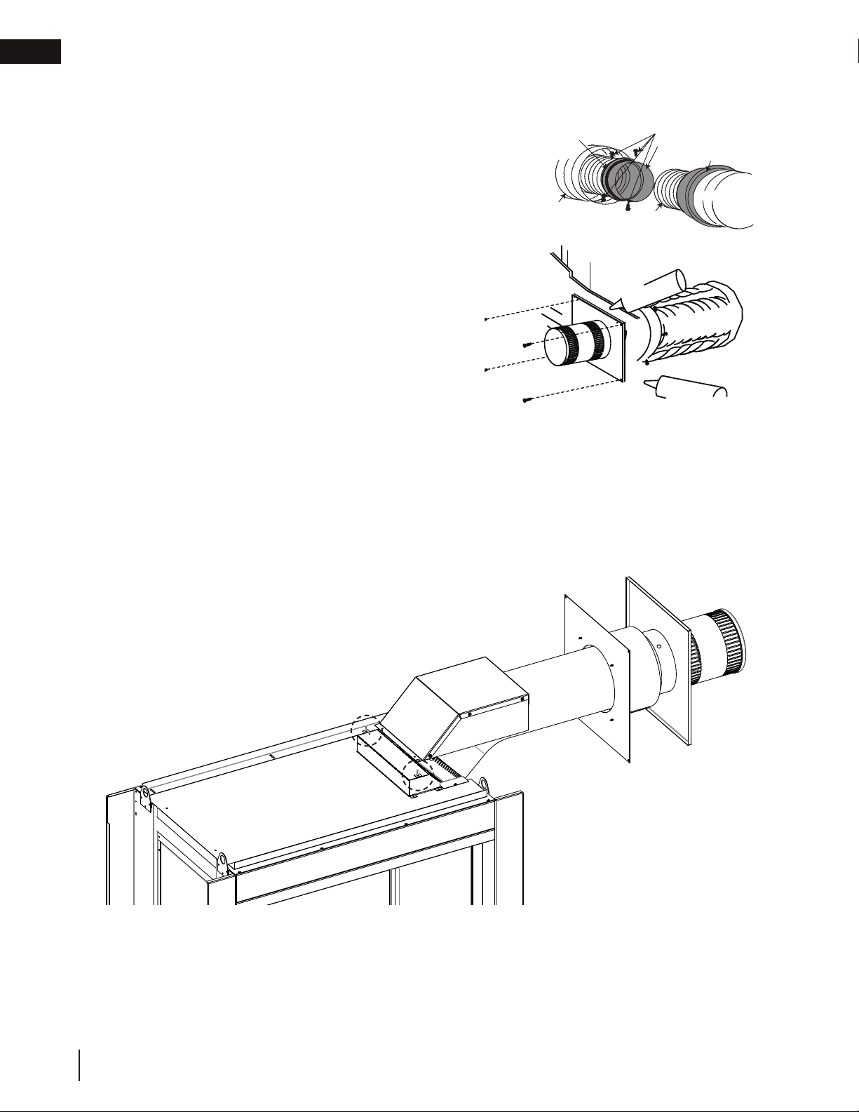
5.3.1 horizontal air terminal installation
A. Stretch the inner fl ex pipe to the required length taking
into account the additional length needed for the fi nished
wall surface. Apply a heavy bead of the red RTV silicone
(W573-0002) (not supplied) to the inner sleeve of the air
terminal. Slip the vent pipe a minimum of 2” (50.8mm)
over the inner sleeve of the air terminal and secure with a
minimum of 3 screws.
B. Using the outer fl ex pipe, slide over the outer combustion
air sleeve of the air terminal and secure with a minimum
of 3 screws. Seal using red RTV silicone (W573-0002)
(not supplied).
C. Insert the vent pipes through the fi restop maintaining
the required clearance to combustibles. Holding the air
terminal (lettering in an upright, readable position), secure
to the exterior wall and make weather tight by sealing
with caulking (not supplied).
D. If more vent pipe needs to be used to reach the fi replace,
couple them together, as illustrated. The vent system
must be supported approximately every 3 feet (0.9m) for
both vertical and horizontal runs. Use non-combustible
strapping to maintain the minimum clearance to
combustibles.
E. Stove Appliances Only: From inside the house, using
Red RTV Silicone (W573-0002) (not supplied), seal
between the vent pipe and the fi restop. Then slide the black trim collar over the vent pipe up to the
fi restop.
The air terminal mounting plate may be recessed into the exterior wall or siding no greater than the
depth of its return fl ange.
18.1
ADD FASTENER TYPE
ADD GRAPHIC
Screws
(Supplied)
2" (50.8mm) Overlap
Outer Flex Pipe
Inner Flex
Pipe
Red RTV Silicone
Caulking
Screws
(Supplied)
2" (50.8mm) Overlap
Outer Flex Pipe
Inner Flex
Pipe
Caulking
Red RTV Silicone
Screws
Inner Coupler
Outer Coupler
Outer Flex
Pipe
Inner Flex
Pipe
Outer Flex
Pipe
Red RTV Silicone
E. The vent shield must be installed only when terminating horizontally. Remove the two screws nearest
the vent collars on the top of the appliance. Align the vent heat shield (supplied) and secure. Adjust
the vent heat shield to touch the firestop spacer, as shown below.
Loading ...
Loading ...
Loading ...