
Loading ...
Loading ...
Loading ...
W415-1285 / L / 10.25.21
EN
10
minimum venting requirements
3.0 minimum venting requirements
You may reduce the appliance from 5/8" venting to 4/7" venting for horizontal and vertical rise applications.
Reducing must be done right off of the appliance and a new firestop spacer will be required.
!
WARNING
• Risk of fi re. Maintain specifi ed air space clearances to vent pipe and appliance.
• The vent system must be supported every 3’(0.9m) for both vertical and horizontal runs. Use support ring assembly
W010-0067 or equivalent non-combustible strapping to maintain the minimum clearance to combustibles for both
vertical and horizontal runs. Spacers are attached to the inner pipe at predetermined intervals to maintain an even air
gap to the outer pipe. This gap is required for safe operation. A spacer is required at the start, middle, and end of each
elbow to ensure this gap is maintained. These spaces must not be removed.
This appliance uses a 5” (127mm) exhaust / 8” (203.2mm) air intake vent pipe system. Refer to the section
applicable to your installation.
For safe and proper operation of the appliance follow the venting instructions exactly. Deviation from the minimum vertical
vent length can create diffi culty in burner start-up and/or carboning. Under extreme vent confi gurations, allow several
minutes (5-15) for the fl ame to stabilize after ignition. Although not a requirement, it is recommended for vent lengths that
pass through unheated spaces (attics, garages, crawl spaces) be insulated with the insulation wrapped in a protective sleeve
to minimize condensation. Provide a means for visually checking the vent connection to the appliance after the appliance is
installed. Use a fi restop, vent pipe shield or attic insulation shield when penetrating interior walls, fl oor or ceiling.
The vent terminal may be painted with a high temperature paint to match exterior colours. Use an outdoor paint suitable for
400°F (200°C). Application and performance of paint is the consumer’s responsibility. Spot testing is recommended.
Connections made by means of an adaptor at the appliance, as well as the connection at the vent terminal must be sealed.
RTV sealant may be used on both the inner exhaust and outer intake vent pipe joints of all other approved vent systems, ex-
cept for the exhaust vent pipe connection to the appliance fl ue collar which must be sealed using the black high temperature
sealant Mill Pac.
For all vent systems is strongly recommend for all installations but required when power venting the appliance, that the outer
air intake joints are sealed using either high temperature silicone (RTV) or a suitable aluminum tape that covers each joint in
the vent system entirely around its circumference. This will ensure the best performance in every application and avoids per-
formance or condensation concerns that may occur in “tightly” constructed homes, particularly those in cold climates.
For optimum fl ame appearance and appliance performance, keep the vent length and number of elbows to a minimum.
The air terminal must remain unobstructed at all times. Examine the air terminal at least once a year to verify that
it is unobstructed and undamaged.
Rigid and fl exible venting systems must not be combined. Different venting manufacturer components must not
be combined.
These vent kits allow for either horizontal or vertical venting of the appliance. The maximum allowable horizontal run is 20
feet (6.1m). The maximum allowable vertical vent length is 40 feet (12.2m). The maximum number of vent connections is two
horizontally or three vertically (excluding the appliance and the air terminal connections) when using fl exible venting.
Horizontal runs may have a 0” (0mm) rise per foot/meter however for optimum performance it is recommended that all
horizontal runs have a minimum 1/4” (21mm) rise per foot/meter using fl exible venting. For safe and proper operation of the
appliance, follow the venting instructions exactly.
A terminal shall not terminate directly above a sidewalk or paved driveway which is located between two single family dwell-
ings and serves both dwellings. Local codes or regulations may require different clearances.
Do not allow the inside liner to bunch up on horizontal or vertical runs and elbows. Keep it pulled tight. A 1¼” (31.8mm) air
gap all around between the inner liner and outer liner is required for safe operation.
Use only Wolf Steel, Metal-Fab, BDM, Simpson Dura-Vent, or Selkirk Direct Temp venting components. Minimum and
maximum vent lengths, for both horizontal and vertical installations, clearances from vent pipes to combustibles and air
terminal locations as set out in this manual apply to all vent systems and must be adhered to. For Metal-Fab, BDM, Simpson
Dura-Vent, or Selkirk Direct Temp, follow the installation procedure provided with the venting components or on the website
for your venting supplier.
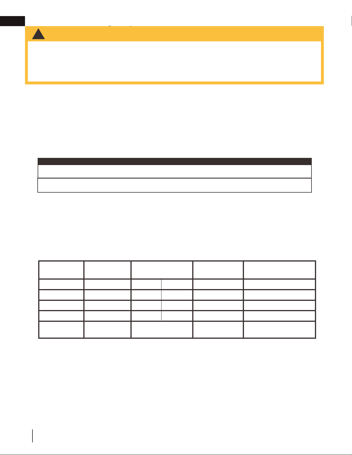
A starter adaptor must be used with the following vent systems and may be purchased through Wolf Steel or from the
corresponding supplier listed below:
If for any reason the vent air intake system is disassembled; reinstall per the instructions provided for the initial
installation.
This appliance must be installed with a continuous connection of exhaust and air intake vent pipes. Utilizing alternate
constructions, such as a chimney as part of the vent system, is not permitted.
note:
This template must be used in conjunction with templates 7.2.1 or 7.2.2, depending on
termination shape (i.e. round, or round and square). See appropriate templates folder.
If approved for use with a power vent kit, state: “This appliance is certifi ed for use with a power vent kit. Con-
tact your local authorized dealer for more information.”
If not, cover with a white box.
DRAFT
Venting System Manufacturer
Starter Adapter
Part Number
Supplier Website
SureSeal Metal-Fab 5DNA Wolf Steel www.mtlfab.com
Direct Vent Pro Simpson DuraVent W175-0170 Wolf Steel www.duravent.com
Pro-Form BDM N/A BDM www.dalsinmfg.com
Direct Temp Selkirk 5DT-AAN Selkirk www.selkirkcorp.com
Ventis
Olympia Chimney
and Venting
VDV-NA05-58F
Olympia Chimney
and Venting
www.olympiachimney.com
!
WARNING
• Risk of fi re. Maintain specifi ed air space clearances to vent pipe and appliance.
• The vent system must be supported every 3’(0.9m) for both vertical and horizontal runs. Use support ring assembly
W010-0067 or equivalent non-combustible strapping to maintain the minimum clearance to combustibles for both
vertical and horizontal runs. Spacers are attached to the inner pipe at predetermined intervals to maintain an even air
gap to the outer pipe. This gap is required for safe operation. A spacer is required at the start, middle, and end of each
elbow to ensure this gap is maintained. These spaces must not be removed.
This appliance uses a 5” (127mm) exhaust / 8” (203.2mm) air intake vent pipe system. Refer to the section
applicable to your installation.
For safe and proper operation of the appliance follow the venting instructions exactly. Deviation from the minimum vertical
vent length can create diffi culty in burner start-up and/or carboning. Under extreme vent confi gurations, allow several
minutes (5-15) for the fl ame to stabilize after ignition. Although not a requirement, it is recommended for vent lengths that
pass through unheated spaces (attics, garages, crawl spaces) be insulated with the insulation wrapped in a protective sleeve
to minimize condensation. Provide a means for visually checking the vent connection to the appliance after the appliance is
installed. Use a fi restop, vent pipe shield or attic insulation shield when penetrating interior walls, fl oor or ceiling.
The vent terminal may be painted with a high temperature paint to match exterior colours. Use an outdoor paint suitable for
400°F (200°C). Application and performance of paint is the consumer’s responsibility. Spot testing is recommended.
Connections made by means of an adaptor at the appliance, as well as the connection at the vent terminal must be sealed.
RTV sealant may be used on both the inner exhaust and outer intake vent pipe joints of all other approved vent systems, ex-
cept for the exhaust vent pipe connection to the appliance fl ue collar which must be sealed using the black high temperature
sealant Mill Pac.
For all vent systems is strongly recommend for all installations but required when power venting the appliance, that the outer
air intake joints are sealed using either high temperature silicone (RTV) or a suitable aluminum tape that covers each joint in
the vent system entirely around its circumference. This will ensure the best performance in every application and avoids per-
formance or condensation concerns that may occur in “tightly” constructed homes, particularly those in cold climates.
For optimum fl ame appearance and appliance performance, keep the vent length and number of elbows to a minimum.
The air terminal must remain unobstructed at all times. Examine the air terminal at least once a year to verify that
it is unobstructed and undamaged.
Rigid and fl exible venting systems must not be combined. Different venting manufacturer components must not
be combined.
These vent kits allow for either horizontal or vertical venting of the appliance. The maximum allowable horizontal run is 20
feet (6.1m). The maximum allowable vertical vent length is 40 feet (12.2m). The maximum number of vent connections is two
horizontally or three vertically (excluding the appliance and the air terminal connections) when using fl exible venting.
Horizontal runs may have a 0” (0mm) rise per foot/meter however for optimum performance it is recommended that all
horizontal runs have a minimum 1/4” (21mm) rise per foot/meter using fl exible venting. For safe and proper operation of the
appliance, follow the venting instructions exactly.
A terminal shall not terminate directly above a sidewalk or paved driveway which is located between two single family dwell-
ings and serves both dwellings. Local codes or regulations may require different clearances.
Do not allow the inside liner to bunch up on horizontal or vertical runs and elbows. Keep it pulled tight. A 1¼” (31.8mm) air
gap all around between the inner liner and outer liner is required for safe operation.
Use only Wolf Steel, Metal-Fab, BDM, Simpson Dura-Vent, or Selkirk Direct Temp venting components. Minimum and
maximum vent lengths, for both horizontal and vertical installations, clearances from vent pipes to combustibles and air
terminal locations as set out in this manual apply to all vent systems and must be adhered to. For Metal-Fab, BDM, Simpson
Dura-Vent, or Selkirk Direct Temp, follow the installation procedure provided with the venting components or on the website
for your venting supplier.
A starter adaptor must be used with the following vent systems and may be purchased through Wolf Steel or from the
corresponding supplier listed below:
If for any reason the vent air intake system is disassembled; reinstall per the instructions provided for the initial
installation.
This appliance must be installed with a continuous connection of exhaust and air intake vent pipes. Utilizing alternate
constructions, such as a chimney as part of the vent system, is not permitted.
note:
This template must be used in conjunction with templates 7.2.1 or 7.2.2, depending on
termination shape (i.e. round, or round and square). See appropriate templates folder.
If approved for use with a power vent kit, state: “This appliance is certifi ed for use with a power vent kit. Con-
tact your local authorized dealer for more information.”
If not, cover with a white box.
DRAFT
Venting System Manufacturer
Starter Adapter
Part Number
Supplier Website
SureSeal Metal-Fab 5DNA Wolf Steel www.mtlfab.com
Direct Vent Pro Simpson DuraVent W175-0170 Wolf Steel www.duravent.com
Pro-Form BDM N/A BDM www.dalsinmfg.com
Direct Temp Selkirk 5DT-AAN Selkirk www.selkirkcorp.com
Ventis
Olympia Chimney
and Venting
VDV-NA05-58F
Olympia Chimney
and Venting
www.olympiachimney.com
4DT-AAN
4DNA
W175-0053
DVR6-STA7
Loading ...
Loading ...
Loading ...