Loading ...
Loading ...
Loading ...
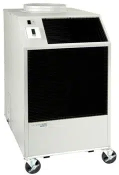
REPLACEMENT PROCEDURE FOR PARTS
IT IS RECOMMENDED THAT ALL OCEANAIRE UNITS BE SERVICED BY A
LICENSED TECHNICIAN
WARNING—TO AVOID INJURY, DISCONNECT UNIT POWER PRIOR TO SERVICING
A. FAN MOTORS
1. Remove cabinet's left-side panel (when looking at the front of the unit).
2. Evaporator fan motor—disconnect evaporator motor wires from evaporator fan
contactor and fan speed rocker switch. Condenser fan motor—disconnect condenser
motor wires from condenser fan contactor.
3. For all model sizes 12, 18 and 36, remove the screws securing motors and inlet-
ring to blower housings (all screws are external and visible), and remove blower wheel-
motor assembly. Remove the blower wheel set screw and disassemble the blower
wheel from the motor shaft and remove the motor.
For models size 60—loosen blower wheel shaft set screw, and remove the screws
securing the motor mount to the blower housing and remove motor and mount.
Remove the motor from the motor mount.
4. Install the new motor, reversing the removal procedure.
B. THERMOSTAT (NO BATTERIES REQUIRED)
1. Pull up from the bottom of the thermostat to remove it from the mounting sub-base, by
gently prying up on the face plate in the slot at the base of the thermostat. Make sure
small thermistor located in the bottom of the thermostat for temperature sensing, is not
bent or damaged.
2. To remove the thermostat sub-base, remove the 2 mounting screws and the 3 wires
(red/yellow/green or red/white black). Make sure the 3 wires do not fall into the
cabinet. Install sub-base by reversing removal procedure.
C. TANK FULL LIGHT
To replace the Condensate Alarm Light on all models, disconnect the wires from the
lamp and bend the tinnerman clip retaining light and pull out. Install new light, reversing
the procedure.
D. CONDENSATE PUMP (ON ALL 5-TON UNITS OR ON UNITS WHERE THE
CONDENSATE PUMP KIT HAS BEEN INSTALLED)
1. Open condensate bucket access door located on lower right side panel and locate the
condensate pump.
2. Remove brackets securing condensate pump in base pan, or condensate tank tray pan
3. Disconnect pump wire leads at Molex connectors. Remove retainer clamp and tubing.
4. Replace pump, install by reversing procedure.
E. HIGH PRESSURE SAFETY SWITCH
1. Remove cabinets left hand side panel, or right rear side panel of Model 60.
2. Remove flare nut that secures capillary to the refrigeration system high pressure side.
A Schrader valve is located in the discharge port, and allows removal without dumping
the refrigerant charge.
3. Remove two screws that retain high pressure switch.
4. Disconnect wire leads from compressor contactor and condensate pump safety switch.
5. Install new High Pressure Control, reversing the procedure.
To gain access to compressor and compressor run capacitor, remove left hand side
panel.
16
Loading ...
Loading ...
Loading ...