Loading ...
Loading ...
Loading ...
Millbrook House, Grange Drive, Hedge End, Southampton, SO30 2DF
0844 879 3587
dimplex.co.uk | gdcgroup.co.uk
47
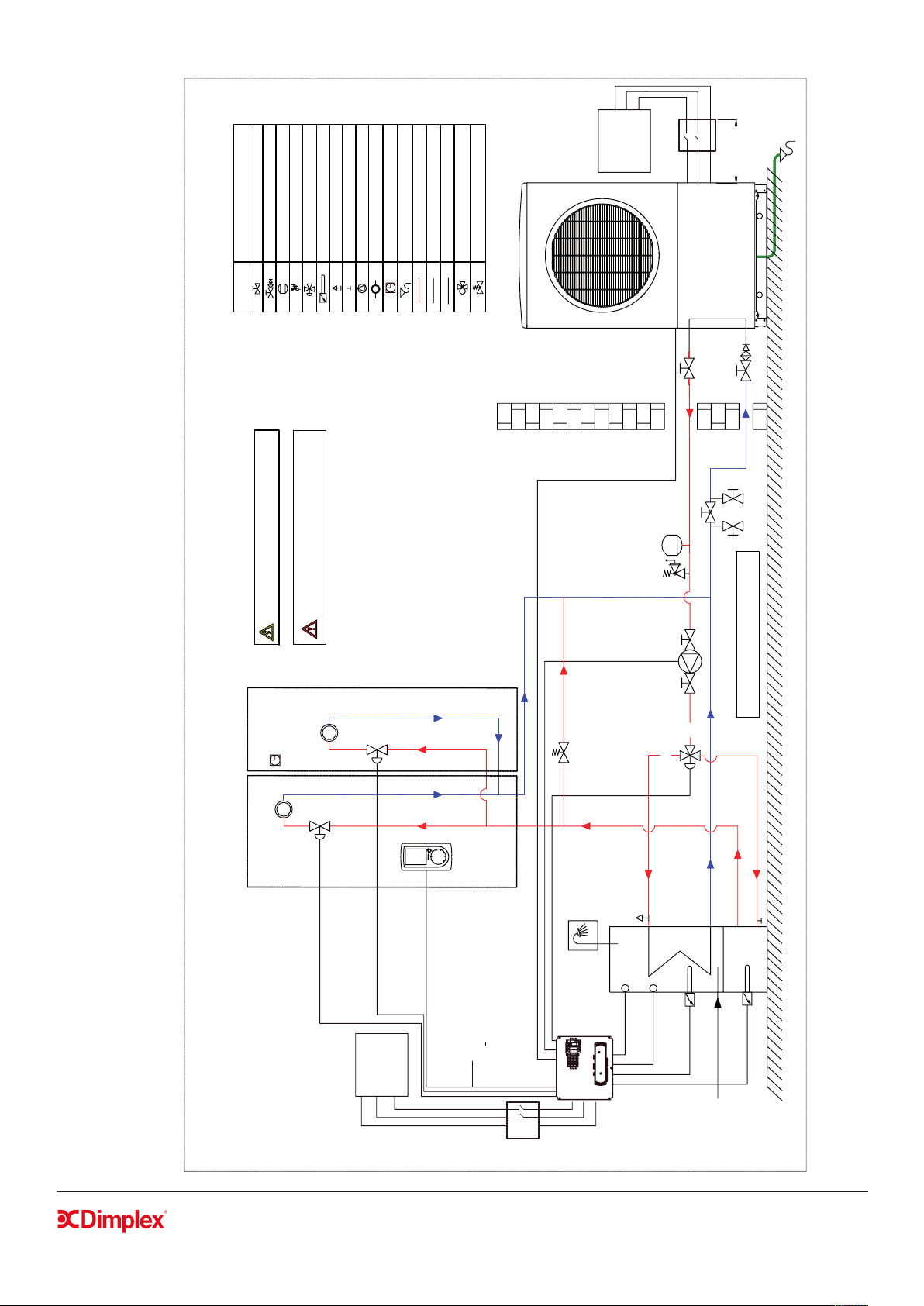
6.4 Schematics - Example 2
A1
A1
A1
A2
A2
10A
RELAY
10A
RELAY
20A
RELAY
20A
RELAY
4A fuse
4A fuse
2A fuse
A2
NTC-Zone4
NTC-Zone3
NTC-Zone2
NTC-Zone1
NTC-DHW
DI 01
DI 03
DI 04
DI 05
N
N
N
E
E
E
DI 02
E
E
N
N
B'
A'
Common
B
A
0Volt Comm
+12V
+230V Comm
+230V Comm
Relay-8
Relay-7
Relay-6
Relay-5
Relay-4
Relay-3
Relay-2
Relay-1
EARTH
NEUTRAL
LIVE
MAINS
POWER
Modbus
Status
MODBUS
SD
System
Status
Refer to Appendices for
detailed wiring of Wiring
centre
Water Module Mains
Supply:
Single Phase
230-240V
50Hz
Heat Pump
Mains Supply:
Single Phase
230-240V
50Hz
DHW Immersion
DHW NTC
Back Up Heater
Alternatives:
- NTC10
- Mechanical Thermostat
if UI Controller NOT used
[
]
Max. 1 Meter
Isolation Switch*
6mm
6mm
6mm
16Amp
Isolation
Switch
E
N
L
L
N
E
*Isolation switch may be 20 Amp for 8kW heat pumps or 40
Amp for 12-16kW heat pumps.
Zone Valve
NOTE: Please ensure that the heat pump circulation
pump is correctly sized for the installation, e.g. minimum
ow is maintained through heat pump at all times
Zone Valve
Zone 1
Room Thermostat
T
NOTE: Fill & Flush connections are not supplied
by Dimplex and must be sourced separately.
T
T
Normally Open
Example 2: Schematic for zones without cir
culating pumps and with a spring-loaded by-pass tted
ZONE 1: Radiators or SmartRads
Mains Cold Feed
Expansion Vessel
Depending on
system volume
Heat Pump
to Heating
A
B
AB
Fill & Flush connections
Spring-loaded by-pass
ZONE 2: Radiators
UI Controller
NTC10 or
mechanical stat.
Isolating Valve
Isolating Valve with Filter & NRV
Expansion Vessel
Safety Valve Combination
Motorised 3-Way Valve
Immersion heater
Air Vent
Drain Off Valve
Pump
Heat Load
Room Thermostat
Drain
Flow
Return Flow
Electrical Connections
3-Way Mixing Valve
Spring-Loaded By-Pass Valve
BUFFER
Drain to Soak Away
SYMBOL
HYDRAULIC SYMBOL
Loading ...
Loading ...
Loading ...