Loading ...
Loading ...
Loading ...
Millbrook House, Grange Drive, Hedge End, Southampton, SO30 2DF
0844 879 3587
dimplex.co.uk | gdcgroup.co.uk
46
A1
A1
A1
A2
A2
10A
RELAY
10A
RELAY
20A
RELAY
20A
RELAY
4A fuse
4A fuse
2A fuse
A2
NTC-Zone4
NTC-Zone3
NTC-Zone2
NTC-Zone1
NTC-DHW
DI 01
DI 03
DI 04
DI 05
N
N
N
E
E
E
DI 02
E
E
N
N
B'
A'
Common
B
A
0Volt Comm
+12V
+230V Comm
+230V Comm
Relay-8
Relay-7
Relay-6
Relay-5
Relay-4
Relay-3
Relay-2
Relay-1
EARTH
NEUTRAL
LIVE
MAINS
POWER
Modbus
Status
MODBUS
SD
System
Status
Refer to Appendices for
detailed wiring of Wiring
centre
Water Module
Mains Supply:
Single Phase
230-240V
50Hz
Heat Pump Mains Supply:
Single Phase
230-240V
50Hz
DHW Immersion
DHW NTC
Back Up Heater
Alternatives:
- NTC10
- Mechanical Thermostat
if UI Controller NOT used
[
]
Zone 1
Room Thermostat
Max. 1 Meter
Isolation Switch*
6mm²
6mm²
6mm²
16Amp
Isolation
Switch
E
N
L
L
N
E
*Isolation switch to suit heat pump model: 20Amp for
8kW heat pumps or 40 Amp for 12-16kW.
Optional
Zone
Valve**
** Additional relay required if pump is controlled by
water module
T
Logic
T
Gate valve for flow adjustment on open
by-pass
If multiple heat emitter circuits are installed, operating
at diff
erent flow and return temperatures (such as
under floor heating and standard radiators), a mixing
valve must be used on low temperature circuits to
prevent high temperature water from entering the
under floor heating manifold.
See
Note
Note
NOTE: If ANY of the zones are using an externally
controlled circulating pump, the open by-pass must
be fitted.
NOTE: Fill & Flush connections are not supplied
by Dimplex and must be sourced separately.
T
T
Normally Open
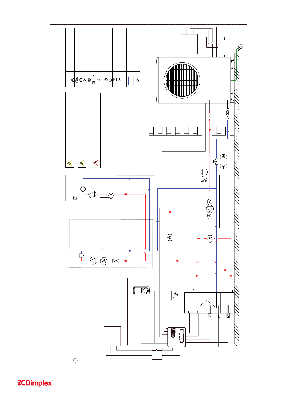
Example 1: Schematic for zones with circulating pump and open by-pass
ZONE 1: UFH
Mains Cold Feed
Expansion Vessel
Depending on
system volume
UI Controller
Heat Pump
to Heating
A
B
AB
Isolating Valve
Isolating Valve with Filter & NRV
Expansion Vessel
Safety Valve Combination
Motorised 3-Way Valve
Immersion heater
Air Vent
Drain Off Valve
Pump
Heat Load
Room Thermostat
Drain
Flow
Return Flow
Electrical Connections
3-Way Mixing Valve
Fill & Flush connections
ZONE 2: Radiators
Volt-free contact on UFH
electronic / logic switch;
To connect to mechanical
thermostat input on the
water module
NTC10 or
mechanical stat.
BUFFER
Drain to Soak Away
SYMBOL
HYDRAULIC SYMBOL
6.3 Schematics - Example 1
Loading ...
Loading ...
Loading ...