Loading ...
Loading ...
Loading ...
Millbrook House, Grange Drive, Hedge End, Southampton, SO30 2DF
0844 879 3587
dimplex.co.uk | gdcgroup.co.uk
41
Figure 34 shows an example of the messages shown in the message list menu.
When a new error occurs, it will appear at the top of the list.
Up to 20 errors can be shown on the list at once, then, if another error occurs, the
oldest error will be pushed off the list to make room for the new error. If the same
error message is being displayed more than once, it may be necessary to check
back through some of the older error messages in order to nd the cause of the
problem.
Figure 34: Message log
NOTE: If a major fault occurs many times, the compressor will go into lock-out mode to prevent any
further damage to the heat pump. In order to resolve this, the power to the compressor will have to be
turned off for at least 2 minutes and turned on again.
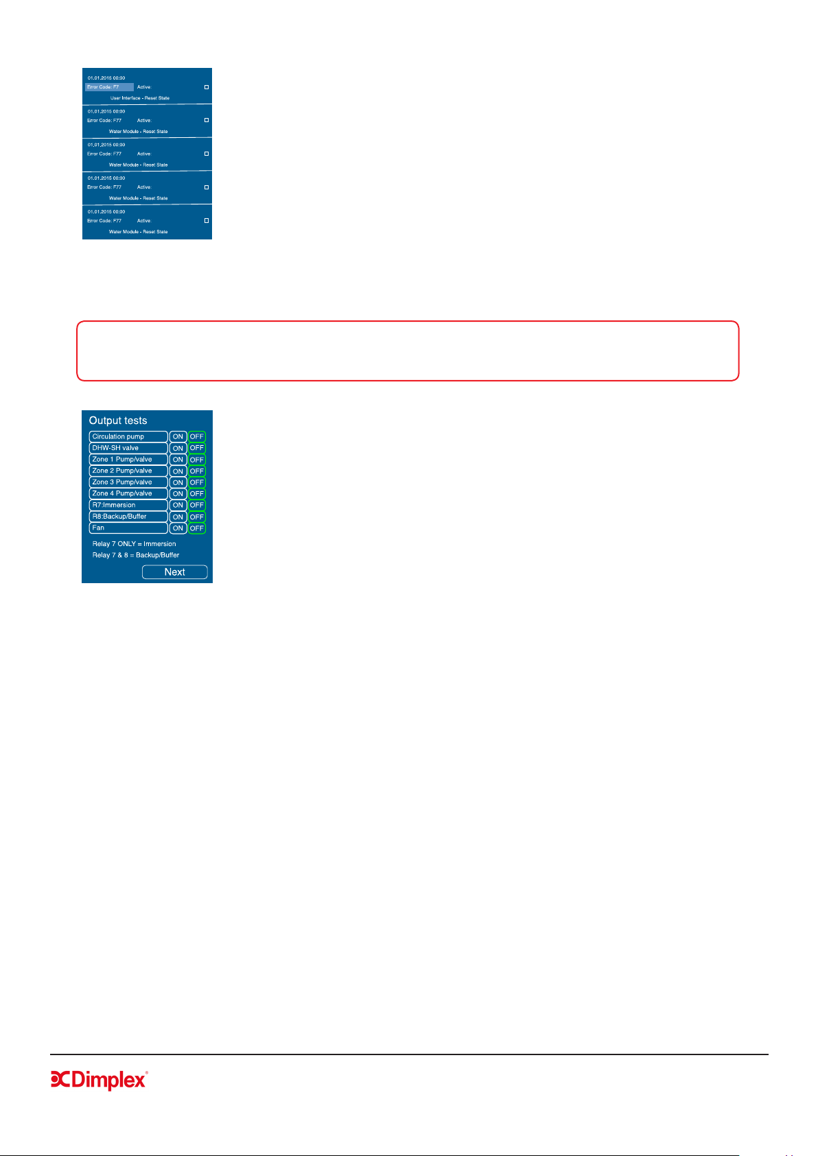
4.5.3 Output Tests
The output tests menu allows you to turn ON/OFF tests on individual
components of the system, as shown in gure 35, and can be accessed once
Electrical Connections (Space Heating) are conrmed.
The relays which control the immersion and backup heater/buffer use
an electric interlocking system, and therefore R7 and R8 must be used
together in order for the backup heater to function. Testing these relays
individually will not reflect this.
Figure 35: Output tests
4.5.4 Defrost
Before running a manual defrost cycle you must ensure the buffer has been isolated from the heating, as
stated by the message on the UI. Selecting ‘Start Defrost’ begins the defrost cycle. The defrost screen will
state the time remaining in the defrost cycle.
A heating water return temperature of 18°C is required for proper defrosting of the evaporator.
4.5.5 Operating data
The operating data menu provides a list of all the system parameters, such as all temperatures, including
each zone set and actual temperatures, ow rate, and heat pump status. If an SD card is present, this data
will be recorded to every message listed.
4.5.6 History
The History menu shows the temporary and permanent run time history of the system. These values
can be reset in order to record run times over a certain time period. Selecting ‘Next’ brings you to the
permanent run time history which cannot be reset unless a software update is installed.
Loading ...
Loading ...
Loading ...