Loading ...
Loading ...
Loading ...
Millbrook House, Grange Drive, Hedge End, Southampton, SO30 2DF
0844 879 3587
dimplex.co.uk | gdcgroup.co.uk
17
1) Check that plinth dimensions are within the required clearances, as per figure 6.
Positioning the heat pump in a conned space, frost hollow or well will result in reduced heat pump
efciency.
The cold air which is expelled by the fan cannot disperse and may be drawn back into the system.
This means that the heat pump may be operating using a lower inlet temperature than what is actually
available from the ambient air.
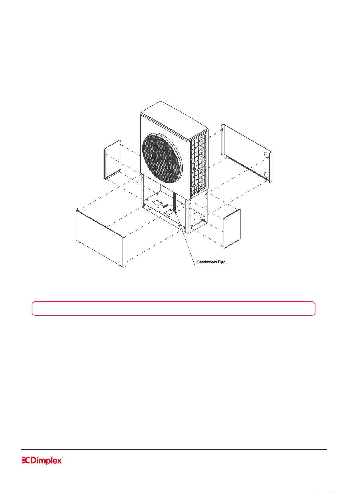
Figure 7: Removing the panels to t xing bolts and condensate pipe
CAUTION: Ensure that the condensate pipe is uncoiled and is running to a drain
2) Remove the heat pump panels to mark drilling holes on plinth.
The heat pump panels must be removed so that the base panel is visible. To do this, remove the screws
and slide the panels downwards and out.
Once the panels are removed, mark the holes for the xing bolts (gure 6), then lift or slide the heat pump
out of the way to drill the holes. Leave the panels off until all xing and positioning of the heat pump, bolts
and condensate pipe have been carried out (steps 3 -4).
3) Run the condensate pipe to an appropriate drain
The condensate drain pipe is coiled up inside the heat pump for protection during transportation. In order
to access this for installation, the panels will need to be removed (see gure 7). The condensate pipe must
be uncoiled and run through the condensate pipe hole in the base panel to the drain.
Loading ...
Loading ...
Loading ...