Loading ...
Loading ...
Loading ...
5
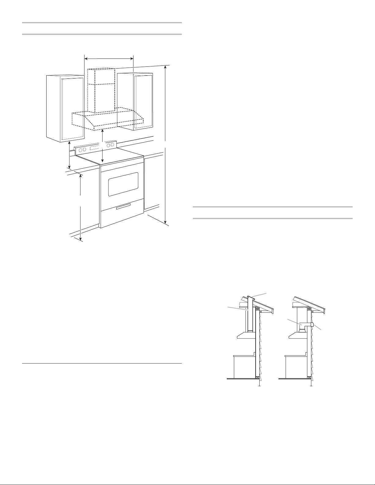
Installation Dimensions
*NOTE: The range hood chimneys are adjustable and designed
to meet varying ceiling or sof t heights depending on the
distance “X” between the bottom of the range hood and the
cooking surface. For higher ceilings, a Chimney Extension Kit is
available from your dealer or an authorized parts distributor. The
chimney extension replaces the upper chimney shipped with the
range hood. See the “Assistance or Service” section to order.
IMPORTANT:
Minimum distance “X”: 24" (61 cm) from electric cooking
surfaces
Minimum distance “X”: 30" (76.2 cm) from gas cooking
surfaces
The chimneys can be adjusted for ceilings between 8' 2³⁄
8
"
(2.5 m) and 8' 10
5
/
16
" (2.7 m) when mounted at 30" (76.2 cm)
height over a gas cooking surface.
The chimneys can be adjusted for ceilings between 7' 8³⁄
8
"
(2.4 m) and 8' 4
5
/
16
" (2.55 m) when mounted at 24" (61 cm)
height over electric cooking surface.
Venting Requirements
■ Vent system must terminate to the outdoors.
■ Do not terminate the vent system in an attic or other
enclosed area.
■ Do not use 4" (10.2 cm) laundry-type wall caps.
■ Use metal vent only. Rigid metal vent is recommended.
Plastic or metal foil vent is not recommended.
■ The length of vent system and number of elbows should be
kept to a minimum to provide ef cient performance.
For the most ef cient and quiet operation:
■ Use no more than three 90° elbows.
■ Make sure there is a minimum of 24" (61.0 cm) of straight
vent between the elbows if more than one elbow is used.
■ Do not install two elbows together.
■ Use clamps to seal all joints in the vent system.
■ The vent system must have a damper. If the roof or wall
cap has a damper, do not use the damper supplied with the
range hood.
■ Use caulking to seal exterior wall or roof opening around
thecap.
■ The size of the vent should be uniform.
Cold weather installations
An additional back draft damper should be installed to minimize
backward cold air ow, and a thermal break should be installed
to minimize conduction of outside temperatures as part of the
vent system. The damper should be on the cold air side of the
thermal break.
The break should be as close as possible to where the vent
system enters the heated portion of the house.
Makeup air
Local building codes may require the use of makeup air systems
when using ventilation systems greater than speci ed CFM of air
movement. The speci ed CFM varies from locale to locale.
Consult your HVAC professional for speci c requirements in
yourarea.
Venting Methods
Typical Internal Blower Motor System Venting Installations
A 10" (25.4 cm) round vent system is needed for installation
(notincluded). The range hood exhaust opening is 10" (25.4 cm)
round.
NOTE: Flexible vent is not recommended. Flexible vent
creates back pressure and air turbulence that greatly reduce
performance.
Vent system can terminate either through the roof or wall.
Tovent through the wall, a 90º elbow is needed.
Roof Venting
Wall Venting
A. Roof cap
B. 10" (25.4 cm)
round vent
A. Wall cap
B. 10" (25.4 cm)
round vent
18" (45.7 cm) min.
clearance upper
cabinet to countertop
36" (91.4 cm)
countertop height
X*
See Note*
36.06" (91.6 cm), or 48.07" (122.1 cm)
or cabinet opening width
(If installed between cabinets)
A
B
A
B
Loading ...
Loading ...
Loading ...